
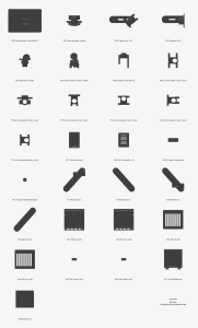
For the week of September 13th-19th, I downloaded SolidWorks from the CMU student catalog, and completed the iteration 1 design of our robotic arm in the SolidWorks Design suite. I broke down frequently used 3D CAD models for other 6-axis 3D printed mechanical arms. The current iteration includes the joints, with some prematurely configured motors and power supply and screw holes.

I designed the main arm’s links, with the base and power supply enclosure. I anticipate the current design for the arm itself to be insufficient for the weight of the motors, so I’ll spend the next week calculating the weight of all components and how much torque they will exert on each joint. The links (the printed section between joints) should be sufficient in size and weight to hold the weight of the arm. I also made sure the measurements for the locations of all 24 cover screws were not blocked, and there was enough spacing between printed components without overlaps.
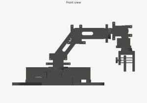
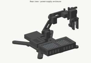
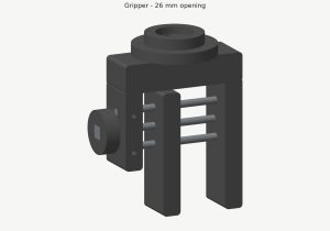
I experimented with pen sleeve designs and ultimately decided on a clawed gripper so the 6th degree of freedom would not limit the pen’s distance from the paper. The gripper now uses one fixed jaw, a sliding jaw, and two 4mm guide rods with an M4 screw that allows the user to manually secure the pen in place. However, this doesn’t allow the robot arm to pick up markers by itself, so we’ll need to tweak this next week.
My iteration 1 CAD and joint, enclosure, and gripper designs, are all scheduled through October 3rd, so it is still in progress and on schedule. I’ve only finished some of the first design and initial load analysis.
For next week, I plan to:
- Experiment and design a counterbalance or something stronger to support the shoulder actuator
- Define joint limits and degrees of freedom for the six axes
- Plan the arm’s path within a fixed workspace that we defined as 0.4m x 0.4m x 0.4m
- Verify and further refine the dimensions of the servos, microcontroller, and power supply, among other parts, from the parts list we defined this week
- Update the SolidWorks printable files assembly