Ludi Cao’s Status Report for 10/23

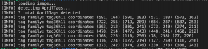
This week I worked on the software portion of the motor controller. I completed the initial setup for the Jetson Xavier, and installed the packages we would need for our project. Since the computer vision algorithms would be run on python, and the Arduino code is in C/C++,  I wrote the communication channel between the Jetson Xavier and the Arduino.

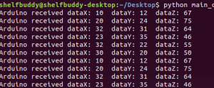
The screenshot shows how the two entities communicate with each other when fed in some data. I also have written the logic of the drive train, specifically the omnidirectional logic for the different motors to move in different directions. I also briefly looked into the software code of adding encoders to our motors. Since the Intel Realsense cannot detect an object in a short distance frame, the drive train would need to travel a fixed distance after applying the computer vision detection from far away. Adding encoders would provide closed-loop feedback to ensure high accuracy. Since the hardware parts have not arrived yet, I am not able to tune any parameters of the skeleton code. Hence, the project is delayed behind schedule, but hopefully, the hardware parts would arrive early next week, and I am able to construct the robot and have an initial test of the motors and drive train accuracy. 

Esther Jang’s Status Report for 10/23

This week, we placed an order for our parts early this week but unfortunately did not receive any of them yet. As a result, I spent time preemptively investigating software aspects of our hardware.

For the claw, I tested controlling a servo through the PWM output on an Arduino board. Although we intend to put them on the Jetson board directly, I tested with the Arduino since I didn’t have access to the Jetson this week. I found that it was very straightforward to run a servo on the Arduino, so we should strongly consider running it there instead of the Jetson if possible.

I also looked into the encoders on the motors and found that they were incremental encoders that have a channel A and channel B pin that needs to be connected to digital pins. In order to keep count of the encoder, we need to compare the signal of the channels with each other as they are out of phase. This also means that we need 5 pins for each motor that uses the encoder – 3 for the motor and 2 for the encoder. As a result, we will likely need to use 3 Arduinos as opposed to our current plan of 2. Overall, using our encoders should not be too difficult as long as we can properly read the pins.

Team Status Report for 10/23

This week, our team finalized our parts order and placed it. We were hoping that at least some of our parts would arrive by the end of the week, but unfortunately did not receive them. We expect to have our parts by the start of the upcoming week and will invest a lot of time to build.

We also had discussions regarding ethics in class and learned a lot in terms of various ethical issues our project may have/cause. For example, we hadn’t considered our laser pointer being misused, our robot damaging the objects it grabs, and if recording others would be problematic.

Bhumika Kapur’s Status Report for 10/23

This week I worked on two things. First, I worked on getting our camera, the Intel Realsense setup. We were able to obtain a new camera with its cable, and get it somewhat working on one of our team member’s laptop, and it also worked well on our TA (Tao’s) laptop. The next step is to connect the camera with the Jetson Xavier and get it setup there.

I also worked on the laser detection algorithm. I tried a few different methods that I found online with varying results. The first algorithm that I tried only used the RGB values of the image, and manipulated these values to calculate the degree of red compared with the other pixel values.  The results are shown below, where the laser is the circular spot:

The next algorithm I used involved using the HSV values and thresholding then, and then anding these values to find the laser in the image.  This method seemed to work, but need more testing to determine the best threshold values. The results are shown below, with the laser in pink:

Overall both algorithms were able to detect the laser in a simple example, but I will need to perform more testing to determine which algorithm is preferred when shining the laser on an object. Next week, I plan to work on setting up the camera and improving on this algorithm.

Ludi Cao’s Status Report for 10/9

At the beginning of the week I had an extensive discussion with my team to finalize the specific hardware we need to order and the associated bill of materials. We realize that budget is a concern, and based on that I slightly modified the base of the robot chassis to be smaller and more compact.

The base is now roughly 35cm * 35cm, where the straight extrusion on the sides are 20cm, and the diagonal extrusions connecting to the wheels are 12cm. Reverting to a smaller size would save up a log of cost material, and also make the linear shaft system steadier. Since the height of our robot is nearly 1 m high, and our claw system would stretch forward to reach an object of 1.5 lbs at max, I was initially concerned that the robot might “tip” forward when reaching out to a heavy object. However, based on the relative distances and weights of components, based on the lever rule in physics, the mass times distance towards the side of the robot is roughly 6 times as heavy than the same calculation done on the object side. Therefore, the need of a counterweight is also removed from my initial prototype of the robot.

I also did some other metrics calculations to confirm our system would meet our technical requirements. We aim to have the robot move at a speed of 0.5 m/s when not performing other computations. Based on our motor specs: 150 rpm and a wheel diameter of 90mm, according to the equations f = 2 pi f and v = rw, we derive that the ideal speed of our robot is 0.7065. Yet, our robot has a considerable weight, so taking a rough 20% deduction, our robot can still travel at a speed of 0.5625 m/s. Hence, I would anticipate our robot would just meet the requirements, and it would be interesting to experiment the results. I also calculated the power our system would consume, and find that our battery can last around 3.5 hours per charge where the robot is operating at full capcacity. This confirms that our robot is efficient enough to be used multiple times.

I am on schedule, although I didn’t find much time to explore the software side of the drivetrain, and we are a bit behind on ordering the materials. Next week our team would focus on the design report, and we would send the materials next Tuesday and hopefully have some parts delivered by then.

Esther Jang’s Status Report for 10/9

Last Sunday, I worked with the team to finish up the design presentation and spent a few hours for presenting it. I ended up presenting on Monday and learned a lot from other groups’ presentations.

Throughout the week, I worked closely with the team to reevaluate and discuss solution ideas. In particular, I helped give feedback to and researched the drivetrain design with Ludi in terms of evaluating motor drivers and compiling an initial bill of materials. After realizing that the motor driver we were initially considering had insufficient current output for our motors, the BTS7960 ended up being the best motor driver solution we could find. We also met up today to thoroughly discuss the hardware solutions we are using and ensured that they synthesized together and had appropriate power systems.

Bill of materials for linear slides + drivetrain:

We also realized that our bill of materials was more costly than anticipated, so we ended up pivoting our linear slides to being powered by Nema 17 stepper motors instead (from the inventory).

Furthermore, I integrated my linear slide system CAD to Ludi’s completed drivetrain CAD (pictured below).

Finally, I have been wrapping up my research for the servo-controlled claw and plan to spend tomorrow CADing it. Most off-the-shelf parts seem to be unfortunately small and I have seen promising claws made from laser cut parts. In particular, I found the following post to be very useful: https://imgur.com/gallery/LpyW3 and the following book chapter: https://link.springer.com/chapter/10.1007/978-1-4302-6838-3_11. The design of such servo claw systems seems to be fairly standardized (claw arms paired by gears and composed of 2 links).

Team Report for 10/9

This week our team discussed and finalized the hardware components. We composed a bill of materials. With the Intel Realsense taking up almost half the budget cost, our current bill of materials would exceed the limit. We communicated this challenge with the professors, and appreciated greatly their understanding, as well as Tao’s kindness to lend his camera for us to experiment.

To satisfy the current draw requirements, we choose to use the BTS7960 DC Stepper Motor Drive https://www.amazon.com/BTS7960-Stepper-H-Bridge-Compatible-Raspberry/dp/B098X4SJR8/ref=sr_1_1?dchild=1&keywords=BTS7960%20DC&qid=1633569262&sr=8-1, since the motors draw an 8.5 A current at max. Different from the L298N spark fun motor drivers, only one motor can be connected to the motor driver instead of two. Hence, we would need six motors in total. We analyzed the pin layout of the Arduino and motor drivers, and realized that each motor driver would require 4 digital pins and 2 PWM pins that need to connect to the Arduino. Since each Arduino has 6 PWM pins as well as 14 digital pins, we would need at least 2 Arduino boards to connect to all of our components. Conveniently, the Jetson Xavier has 2 5V USB outputs, which can connect to 2 Arduino boards at max. We finalized our selection of the battery as well. Our design should meet the technical and physical requirements, and we are ready to compose our design report due next week. 

Bhumika Kapur’s Status Report for 10/9

This week I worked on a few tasks. First, I worked with my teammates to complete the design presentation. We had to reevaluate some of our requirements and solution approaches for the presentation. We also discussed our solution approach in detail and researched how each component would connect to other components.

I also received the Intel RealSense camera from Tao this week, and spent some time trying to set it up. I was able to get it connected to my laptop and using a VM, I am able to access the camera. The next step is to setup the camera in the Intel RealSense Viewer. I have been attempting to get the camera setup in the viewer, but the viewer crashes whenever I open it, so I will need to debug that this week.

I also worked on the April tag detection code. As I mentioned last week April tag code is originally in Java/C so I followed some tutorials online in Python, which I am most familiar with, to get the software setup. Currently I am able to draw a bounding box around the April tag, detect the specific family the tag is from, and output the exact coordinates of the tag in the image. My next steps are to combine this with the data that I would receive from the camera to output the exact location of the April tag so the robot can navigate to it. I hope to do that next week.

Example image/output:


Esther Jang’s Status Report for 10/2

This week, I spent most of my time doing CAD on Solidworks or researching design options.

I first made considerations for our linear actuation system. Given the height requirement of our robot, I thought it would be best to use a linear motion kit and decided to use the following pulley system described here: https://docs.revrobotics.com/15mm/linear-motion-kit. The primary motivation behind this selection was that it was built to sustain a multi-level cascading height that could reach our height requirement of 3 ft. Furthermore, it is very mounting-friendly for other parts (such as our claw or drivetrain) and price-accessible. This is better than other alternatives that are often significantly more expensive or cannot meet our height requirement (most common problem). I assembled the CAD for this part by using the standard part library from the vendor. The process was time-consuming as I had to relearn how to assemble with CAD, but I believe that it was valuable experience to help me with CADing the remainder of my part of the project.

Linear slide system CAD render (based on https://docs.revrobotics.com/15mm/linear-motion-kit/three-stage-cascading-lift)

I also invested several hours into checking the viability of using a vacuum suction gripper, following feedback from a recent meeting to consider it. Using a vacuum suction gripper was a good idea because of the benefit of reducing room for error and for emulating current industry solutions of our idea (i.e. https://www.youtube.com/watch?v=zeKfvUVbO3g&t=4s&ab_channel=IAMRobotics). The main issues I was facing in my research were the following:

  • Limited amount of information about the performance of diy suction gripper kits: Most vendors make claims about the performance (i.e. how much load the system can carry), so this was the only basis we could make a decision off of. I was unable to find much solid, unbiased research to support these numbers quantitatively aside from anecdotal videos of performance.
  • Limited availability of diy suction gripper kits: Almost all diys I could find were using some version of a standardized suction gripper kit that seems to only be sold from Chinese vendors and with an estimated shipping time of 1 month out in early Nov. There was also a single vendor on Robotshop that sold a potentially promising suction gripper system that uses a syringe+servo system instead of an air pump. The description claimed to be able to have a load of 3oz (0.21lbs) which could potentially be too poor of a performance.

Overall, the vacuum suction idea ended up being too high risk given its limited availability, so we decided to safely abandon the idea in favor for a claw.

Currently, I plan to use a claw system that is similar to off-the-shelf standard grippers (such as https://www.robotshop.com/en/actobotics-perpendicular-standard-gripper-kit-b.html) that is powered by a servo. The reasonably priced off-the-shelf parts do not seem to meet our requirements for objects to grab (small size maximum grip size of 4in and unknown (but likely very light) weights. My current research seems to indicate that CADing and laser cutting the claw is likely the correct direction, so I will continue to look in this direction (i.e. https://imgur.com/gallery/LpyW3).

I believe I am on track as the design research I did was thorough in making sure the chosen designs meet our requirements and are reasonably priced. I will be finalizing the claw idea and expanding upon the electronic hardware evaluation done last week by early tomorrow (in time for the design presentation).

Ludi Cao’s Status Report for 10/2

This week I finalized the main hardware structures for our robot. Esther and I agreed to use components from the Rev Robotics vendor. This is because the components are compatible, and we would not have to worry about booking inconsistent sizes or models from different suppliers. In addition, Rev Robotics has well-maintained documentation and CAD models for each part, which makes designing the chassis much more convenient. Since our robot would be 3 ft in height, I plan to design my chassis with roughly a size frame of 60cm x 60cm, along with 90mm diameter omni wheels. However, I haven’t done an extensive weight/force calculation yet to gauge the appropriate frame. I would invest in the details more throughout next week leading up to the design report, and this might likely change. Most of my progress this week has been prototyping / CADing the chassis frame. At first, I decided to use motors from other vendors, but realized that finding an adequate motor mount that fits other components in the Rev Robotics kit is very difficult. I also learned the importance of designing. While assembling the parts, I realized that the screw header from the motor mount would interfere with the wheels, due to the motor rod being too short for multiple components to fit on. This would be something I might not have thought of if I went straight into implementation, especially since these are the steps listed on the documentation. After choosing a new pair of mounts, and avoiding the usage of some pins, fortunately the issue is resolved.


Attached is the CAD for the wheel chassis so far. I haven’t included some of the screws yet, but the overall design is not affected. I am using the Jetson Nano here in place of the Jetson Xavier since I couldn’t find CAD models for the latter, but since the overall dimensions for the two are the same, this is used for reference. The back of the robot represents a counterweight that helps balance the robot, since the claw would extrude forward to reach an object. I haven’t decided on what weights to use yet, and this would be determined through calculations of the force relationships, as well as experiments. I still need to include the motor drives, the H bridges, and the connections to the motors for this prototype to be finished, which I would continue to work on for next week. I would start ordering components next week, and research more on the quantitative analysis of our system design, especially the force/torque, and power requirements/limits. This result would lead to our design report. If I find time, I would start my research in the programming aspect of motor control, or start building the chassis if parts come in early enough and the design feedback is positive, where not much needs to be changed