This week our team worked together to integrate the subcomponents of the robot. First, we experimented with the MPU 6050 gyroscope but later realized that the IMU would have a better prediction. We also built the testing shelves for the robot. We then performed integration of moving to the basket, orienting with the shelf, driving up to the basket, recognizing a laser-pointed object, and retrieval of the object. There are still some issues with the computer vision laser-pointing technique as noise is still being picked up, but overall the project is promising. Hopefully, by Thanksgiving break, the laser pointer recognition can be improved, and a preliminary demo can be given.
Esther Jang’s Status Report for 11/20
This week, I worked with the team to do testing as described in the weekly status report. We are currently incrementally programming the various steps of our robot’s navigation process which has required a lot of on-hands testing and discussions for problem solving. With Thanksgiving break approaching, we are hoping to be done with our target implementation soon, which may be possible with our current progress.
Team Status Report for 11/20
This week our team worked on the navigation and retrieval process of the robot. After speaking with Tamal and Tao we reconsidered our robot’s sequence of steps, and worked on the code required for the robot’s navigation and retrieval. This week, we accomplished the following:
- We wrote code for our robot to rotate 360 degrees in search for the April Tag on the basket. Once the robot detects the Tag on the basket, it rotates to be perpendicular to the basket, and drives up the basket stopping about 1 foot in front of the basket.
- Next we wrote code for our robot to rotate and look for the April Tag on the shelf. Once the tag on the shelf is detected, the robot rotates so it is facing perpendicular to the shelf.
- Then, the robot moves around the basket, and drives up to the shelf, stopping about 1 foot from the shelf.
- Then the linear slides extend until they reach the maximum height, about three feet.
- Once the slides are extended, the robot searches for the laser pointer.
We accomplished the above steps this week, and a video can be seen below:
Currently the robot is sometimes able to center itself to the item with the laser and drive towards it, but this step does not work all of the time. Thus, next week we plan on improving the item detection step, and working on the grabbing the object from the shelf.
Bhumika Kapur’s Status Report for 11/20
This week I worked with my teammates on the navigation and retrieval process of the robot. We all worked together on those tasks and our progress is detailed in the team status report. I also worked on improving the CV component of the project as there are some errors that occasionally occur in different lighting conditions, but I am hoping those will be resolved with more testing soon. Next week I will continue to work with my team on the robot and our final presentation,
Ludi Cao’s Status Report for 11/13
At the beginning of the week, I implemented the motor control code for the wheel chassis on the robot. The following video was performed during the interim demo.
After the demo, I worked with Esther and Bhumika to integrate our subsystems. I first experimented with the relationship between the motor spin time and the distance it would travel. The robot can accurately travel a specific small distance without much drift in all directions. Then, we incorporated the computer vision subsystem to work on various navigation sub-components. The robot can move towards an apriltag from an initial position at a tilted angle. The robot would first rotate to face parallel to the apriltag, center itself horizontally, and then move towards the apriltag, based on the location and angle coordinates of the camera. The other subsystem we worked together as a group is laser pointer recognition, centering the robot to the tagged object, and then moving forward towards the robot. Next week, we would add an IMU sensor for more precise movement of the robot in case of drift, and work on the remaining subcomponents: retrieving the item from the shelf and returning to the basket.
Esther Jang’s Status Report 11/13
Since my subsystems were completed and have been consistently performing as normal since last week, I did not make any changes to the linear slides nor claw subsystems. All of my work for the week was done with the rest of the team to help implement navigation/integration as described in the team’s weekly status report.
Team Status Report for 11/13
This past week, the team primarily worked collaboratively to start autonomizing the robot. We also had demos during class time where we were able to show the subsystems and receive feedback.
Originally, the code that runs the subsystems for the chassis, slide, and claw systems were separate. When we tried combining them together, we realized that the servo library for the Arduino disables 2 PWM pins on the board (after experiencing a strange bug where some motors stopped moving). This meant that we could not run our entire system together across 2 boards since we needed to use all 12 PWM pins for our 6 motors. We concluded that we either needed to get a servo shield to connect to servo to the Xavier (the Xavier has GPIO pins so the servo cannot be directly connected) or get a larger Arduino board. We were also running into some slight communication delay issues for our chassis with one motor being on a separate Arduino from the others. Hence, we ended up replacing our 2 Arduino Unos with one Arduino Mega 2560 board. Since the Mega board has 54 digital pins and 15 PWM pins, we were able to run all our subsystems on the single board and also eliminated the communication issues across the 2 boards.
For our navigation code, we first focused on being able to get the robot to navigate to an april tag autonomously. Currently, we are relying on being able to rotate and move the robot based on powering the motors on the chassis for a given amount of time. In our tests, we were able to consistently replicate having 1 second of running motors to 0.25m of movement. However, the translational movement is prone to some drift and acceleration over larger distances. Hence, we plan to mostly keep our movements incremental and purchase an IMU to help with drifting disorientations.
Video of 1 second movement to 0.25m translation
Similarly, we found that we were able to fairly consistently get the robot to rotate angles of movement by proportionally associating power on time to our rotational movement.
We then took these concepts and were able to get our robot to navigate to an April tag that is in its field of view. The April tag provides the horizontal and depth distance from the camera center as well as the yaw angle of rotation. Using this information, we wrote an algorithm for our robot to first detect the April tag, rotate itself so it is parallel-y facing the tag, translate horizontally in front of the tag, and translate depth-wise up to the tag. We still ran into a few drifting issues that we are hoping to resolve with an IMU but got results that generally performed well.
Our plan is to have an april tag on the shelf and on the basket so that the robot can be able to navigate both to and from the shelf this way.
We then focused on being able to scan a shelf for the laser-pointed object. To do this, the robot uses edge-detection to get the bounding boxes of the objects in front of it as well as the laser point detection algorithm. It can then determine which object is being selected and center itself in front of it for grabbing.
We tested this with a setup composing 2 styrofoam boards found in the lab to replicate a shelf. We placed one board flat on 2 chairs and the other board vertically at a 90-degree angle in the back.
Video of centering to laser pointed box (difficult to see in the video but the right-most item has a laser point on it):
Our next steps are to get the robot to actually grab the appropriate object and combine our algorithms. We also plan on purchasing a few items that we believe will help us improve our current implementation such as an IMU for drift-related issues and a battery connector converter to account for the Xavier’s unconventional battery jack port (we have been unable to run the Xavier with a battery because of this issue). The camera is also currently just taped onto the claw since we are still writing our navigation implementation, but we will get it mounted at a place that is most appropriate based on our completed implementation. Finally, we plan to continue to improve on our implementation and be fully ready for testing by the end of the next week at the latest.
Bhumika Kapur’s Status Report 11/13
This week I worked on both the edge detection and April tag code.
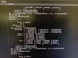
Firstly, I improved the April tag detection so the algorithm is able to detect an April tag from the camera’s stream, and return the center and coordinates of the tag along with the pose matrix, which allows us to calculate the distance to the tag and the angle. The results of this are shown below:
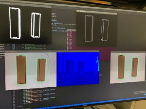
Second, I worked on improving the edge detection code, to get a bounding box around the different boxes visible in the camera’s stream. The bounding box also allows us to get the exact location of the box, which we will later use to actually retrieve the object. The results of this are shown below:
Finally, I worked with my team on the navigation of the robot. By combining our individual components our robot can now travel to the exact location of the April tag which marks the shelf. The robot is also able to drive up to the exact location of the item which has the laser point on it, and center itself to the object. Over the next week I plan to continue working with my team to finish up the final steps of our implementation.
Ludi Cao’s Status Report for 11/6
This week I worked mainly on the navigation code and some design of the middle board which places objects. I implemented a program where the Jetson sends directions to the two Arduinos, and the motors spin accordingly based on omnidirectional rules. Attached is a video that demonstrates this behavior.
One promising thing I noticed is that, even though each motor is controlled by a separate motor driver, and the four motors interface with different Arduinos, the motors change direction at the same time. However, I do notice that there is a lag between the time the Jetson sends commands to the Arduinos, and when the motors respond to the command. Hence, this is something to be aware of when the Jetson sends information to the motors potentially about a frame captured slightly earlier.
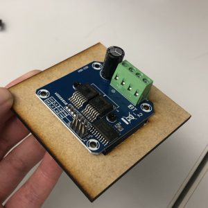
Esther and I also did a bit of designing of the board to place the various electronic parts. We think that we don’t necessarily have to mount everything on top of the board, but it is useful to create mounting holes for the motor shield, since there is a heat sink that gives it some height. We managed to measure out the dimensions for the motor shield. Attached is an image to show how the motor shield would be mounted. I would work on engraving the motor shields dimensions into the larger board, and hopefully have it laser cut on Monday or Wednesday.
To test how the robot currently navigates, I temporarily used a cardboard to place various electronics. Since I am testing in the lab room, I ran into the issue that the floor might have too little friction, resulting in the wheels spinning at different speeds. The robot would not go in the direction as intended. We plan to add a foam-like structure on the wheels to increase friction. I would also look further into my code and the mechanical structure of the robot to see if there’s anything to troubleshoot.
For next week, I plan to debug the issues about navigation ideally before the demo, laser cut the board to place the electronic components, and work with Bhumika to integrate computer vision into navigation. Hopefully, the robot can respond to camera data and move accordingly.
Esther Jang’s Status Report for 11/6
This week, I worked on mounting and motorizing the linear slides on the robot. Both slides were mounted mirroring one another on the chassis. The pulleys were strung with a string that was attached to the motor that would pull the slides. I found that the motor alone was insufficient for lowering the slides, so I added some tension to pull the slides down when unwinding the string by attaching surgical tube between adjacent slides.
Overall, the slides were able to successfully extend and detract with a bar mounted between them as shown in the following clip:
There are some slight issues with detracting fully which I think is related to minor tension issues. The slides were able to individually detract otherwise.
At one point in the week, one set of slides were completely stuck and required significant disassembly to resolve. In order to fix and further help avoid this issue, lubricant grease was applied to the slides.
Finally, I also tested the claws this week and found one to have significantly better grip range and torque than the other. Using the servo code written a few weeks ago, I was able to get the claw to grab a small, light box. The claw was also mounted onto the end of the slides.