Team Status Report for 3/16

General updates

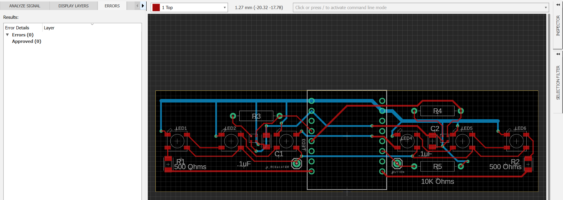
Due to significant differences in different sound apps reading the same sound, we decided to narrow down the variables involved by all downloading the same app and placing votes as close together as possible. We still get different dBs for the same app, but we also have different phones/mics, which we can’t control. The standard deviation between us is about 3 to 4 dB, which is outside of our desired range of being within 2dB of accuracy. The problem is, we don’t even know who is the most accurate, only that we are precise. Luckily, Prof Sullivan offered to give us a more trustworthy decibel meter starting the week after next, which can hopefully clear up this debate permanently. We will be taking it to practice sessions with the music students that we have been coordinating times with.

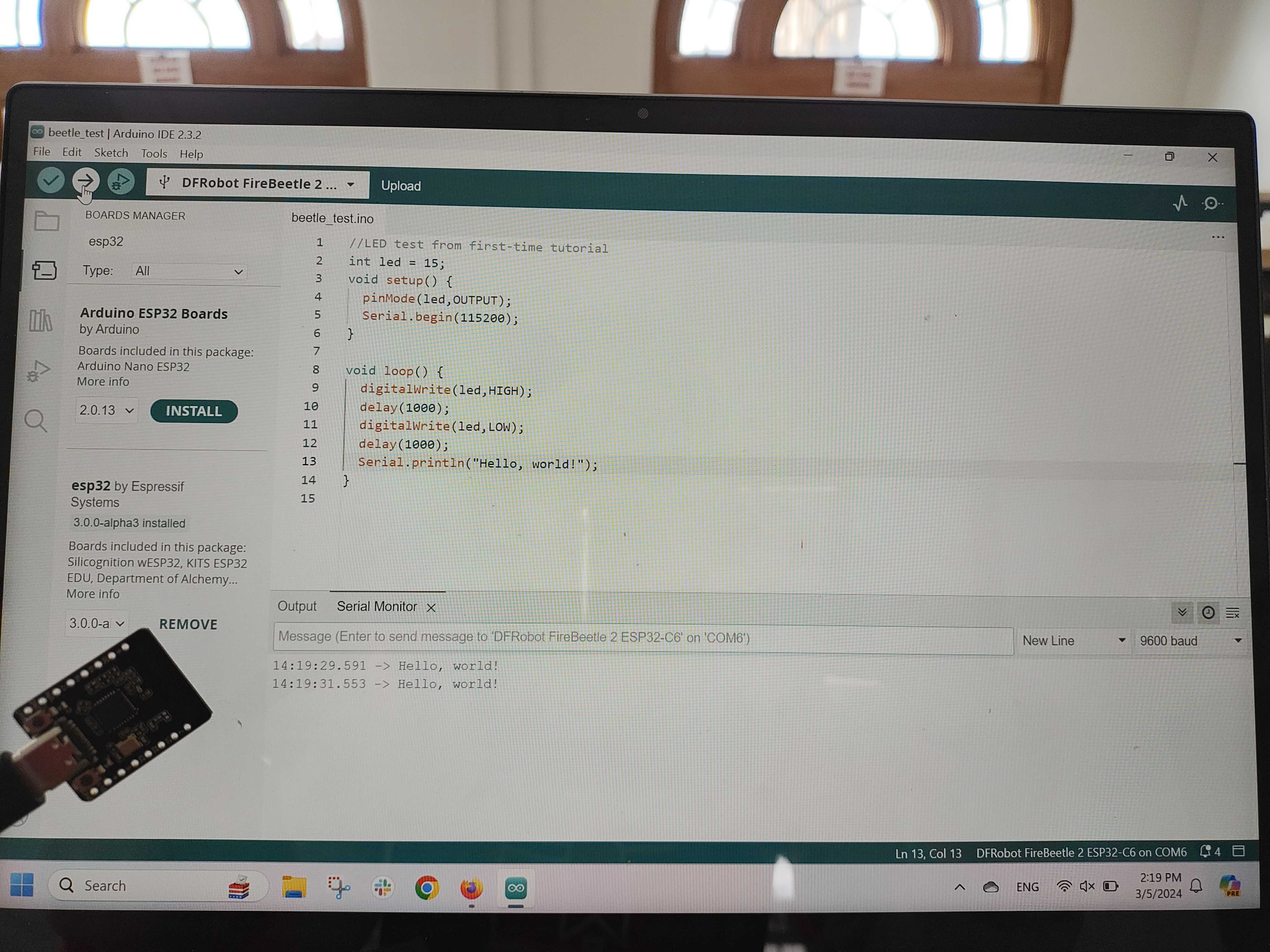
We also discussed microphone signal processing in our weekly meeting with Prof Fedder. Since microphone noise is negligible compared to the loudness we’re measuring, and we’re only interested in measuring loudness, filtering out noise probably isn’t necessary. A basic version of mic signal processing would measure the amplitude of the incoming signal a certain number of times per second and linearly scale that to dB levels. A more sophisticated version would use an FFT (https://projecthub.arduino.cc/abhilashpatel121/easyfft-fast-fourier-transform-fft-for-arduino-03724d) to see the “spikes” within the frequency range we are interested in, and take the maximum of the spike amplitudes. The problem with either version is that in order to account for frequency overtones and Nyquist’s theorem, we need to sample thousands of times per second. This might be computationally expensive.

What are the most significant risks that could jeopardize the success of the project? How are these risks being managed? What contingency plans are ready?

The PCB doesn’t get here on time (expected arrival Tuesday). Given how much this delay has blocked our progress this first iteration, when we order the final (flex) PCB, we plan to pay extra for fast shipping instead of regular shipping, since we have enough left in our budget.

Were any changes made to the existing design of the system (requirements, block diagram, system spec, etc)? Why was this change necessary, what costs does the change incur, and how will these costs be mitigated going forward?

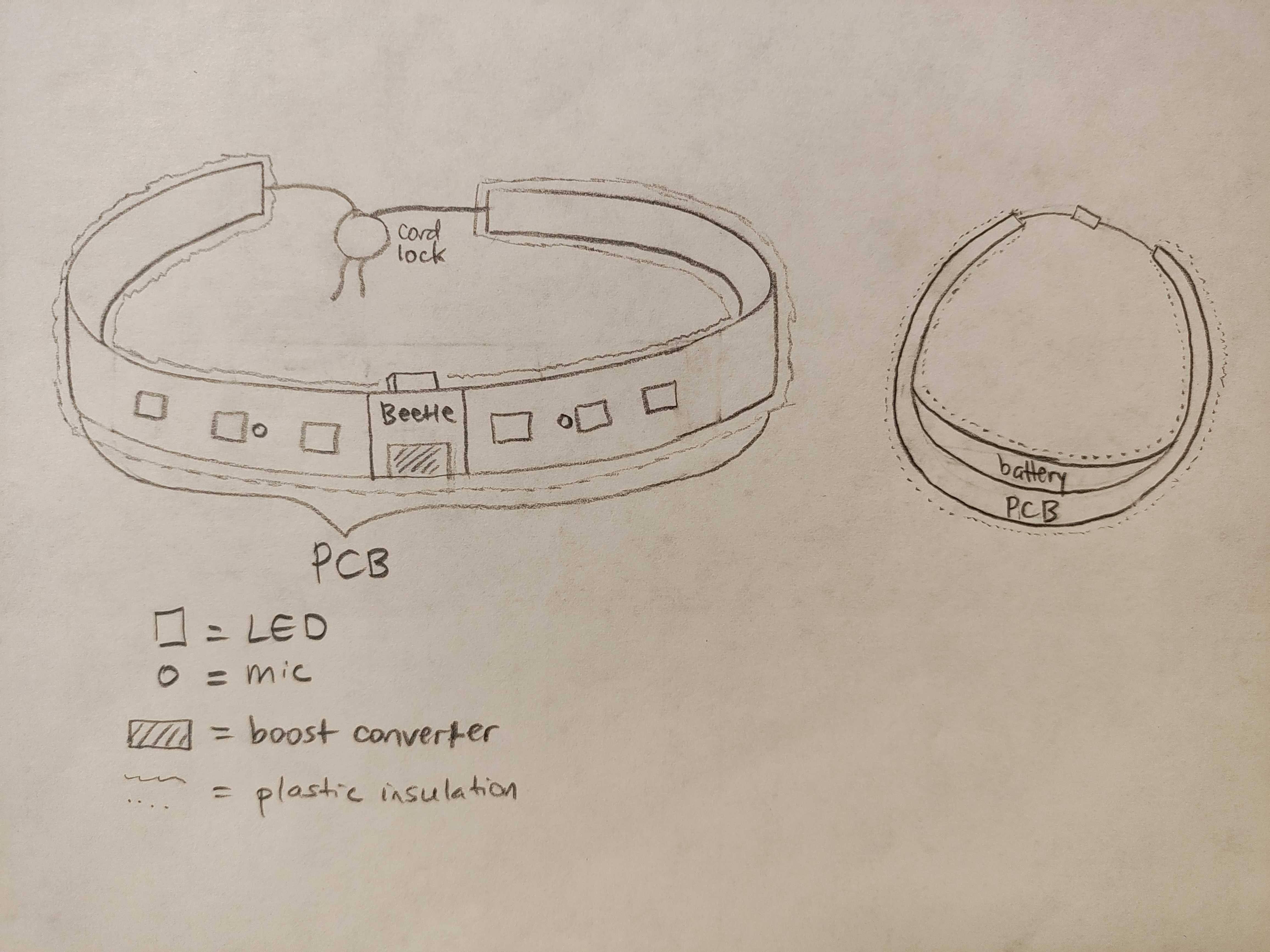
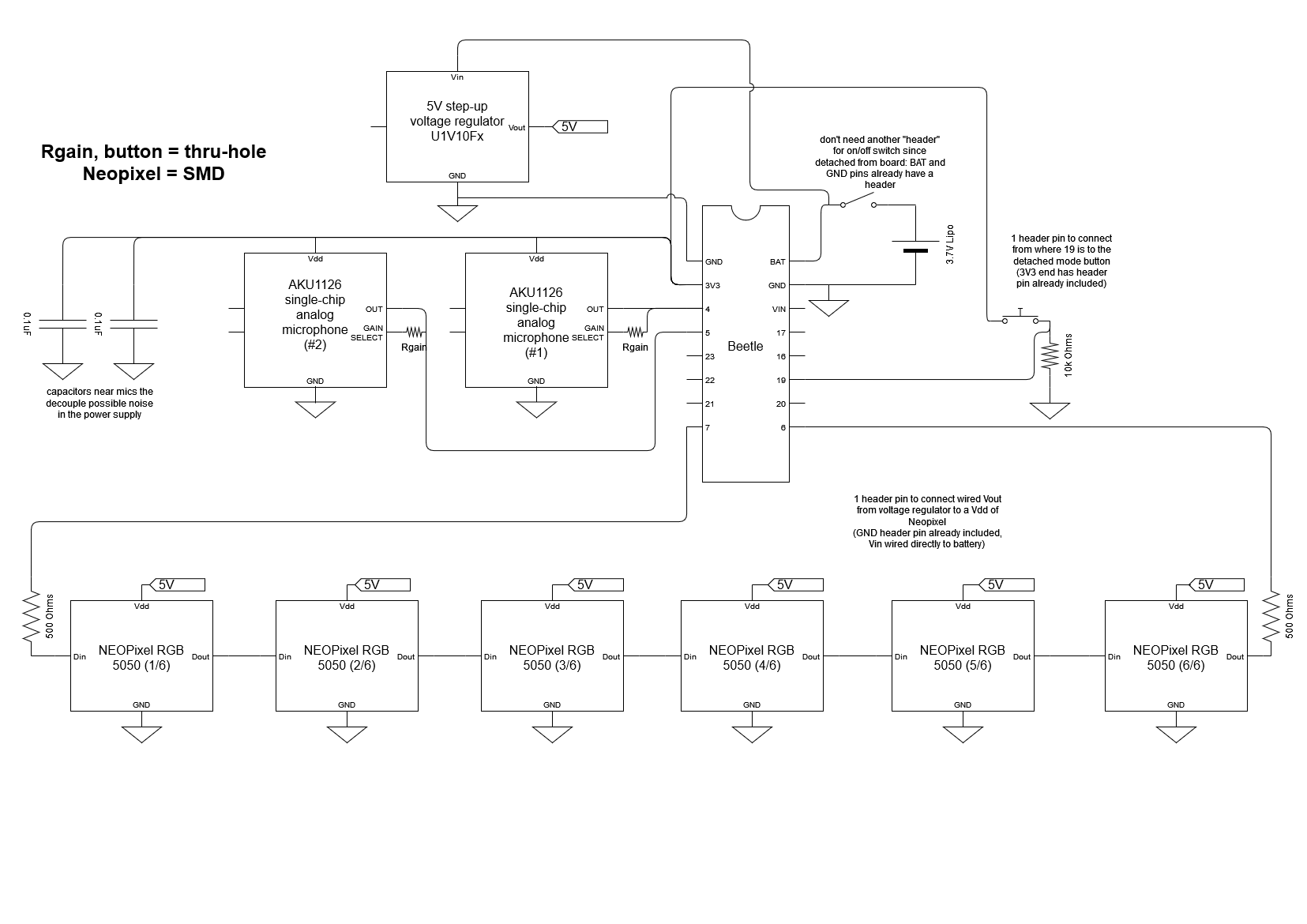
No changes were made to the existing design. We’re still planning to order a flex PCB with the final design once we have tested the rigid prototype PCB and noted what changes need to be made.

Provide an updated schedule if changes have occurred.

The schedule has been updated. PCB creation/delivery took longer than expected, and a lot of tasks depend on us having the PCB, since a lot of the components are tiny SMD things that we can’t try to do by hand.

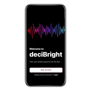
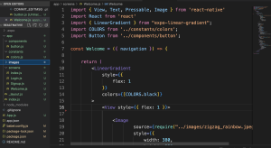
This is also the place to put some photos of your progress or to brag about a component you got working.

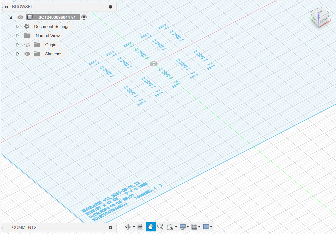
Here is a picture of the stencil for our PCB.

A tilted view of the PCB stencil in light blue.

Gantt Chart changes:

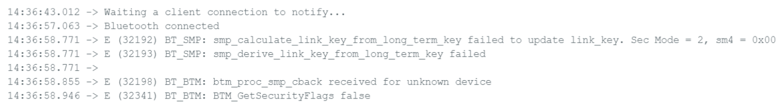
Software: Due to difficulties in getting the Bluetooth connection to work on the mobile app, we have allocated an extra half a week to figuring it out. Additionally, the decibel reading display and visualization algorithms have been moved forward so that they can be done by the interim demo (4/1). Since full integration of the bracelet and the web app won’t occur until after the interim demo, these pages will be displaying information using dummy data.

Hardware: Electronic prototyping/PCB assembly and microphone signal processing have been moved forward by a half-week as well, because we can’t do much without the PCB being physically here.

Katherine’s Status Report for 3/16

To correct an error from last week: this week, I was supposed to be working on microphone signal processing, not LED signal setup, in addition to electronic prototyping.

In our weekly check-in discussion, I got an idea of how microphone signal processing is going to work in the context of our project. My eventual plan to determine the necessary sampling frequency is to test the bracelet microphones by sampling at the higher rate (including all expected overtones) when at a music practice. I hypothesize that the overtone frequencies will tend to be softer/have smaller amplitudes, which will reduce the frequency range we would have to work with and therefore our required sampling speed as well.

Some of my progress is on schedule, while other parts are behind.

The on-schedule elements are as follows. I wrote the logic for the ratio of microphone decibel values affecting the color of each LED when in directionality mode. When in directionality mode, the LEDs light according to a dB value that is a weighted average of the dB value for either direction (the weights differ depending on the LED’s location relative to either microphone). The farthest and second-closest LEDs from the Beetle on each side will display the color value corresponding to their side’s microphone input, while the LEDs closest to the Beetle will display a color value corresponding to ⅔ of their side’s microphone value added to ⅓ of the other side’s microphone value. When not in directionality mode, all LEDs will display a color corresponding to the average of the two microphone input amplitudes. The logic for determining direction already exists (I believe last week’s “how determining direction… will work” was in the context of LED colors?). For the record, it takes the ratio of the amplitude from each microphone input and assumes that a sound equidistant from each mic will have a 1:1 L:R ratio, while a sound completely from the left or right will have a ratio of X:1 or 1:X (X being the maximum ratio). It then scales based on the ratio of input amplitudes to find an angle value between these. X will be iterated on during directionality testing.

I am behind on establishing the Beetle-Bluetooth connection. According to https://github.com/espressif/esp-idf/issues/6550, in order to establish a connection to my phone with the correct security, I need to turn on secure simple pairing or change the mode to mixed mode; I need to research if it is recommended to change these features of the Beetle’s Bluetooth module. Further research suggests that it would be useful to connect to the Beetle through a third-party app (https://wiki.dfrobot.com/DFRobot_Bluetooth_4.1__BLE__User_Guide#target_2 states that it is required for Bluetooth 4.1, and our Beetle uses Bluetooth 5), but none of the apps I tried could recognize the Beetle.

Tasks that depend on having the PCB are also behind. The PCB is scheduled to arrive on Tuesday. Once the PCB is assembled, I plan to continue work on electronic prototyping (including researching the Beetle-Bluetooth issue) and microphone signal processing. I will also help with testing the webapp if necessary and with visualizing decibel readings if time permits.

Lucy’s Status Report for 3/16

What did you personally accomplish this week on the project? Give files or photos that demonstrate your progress. Prove to the reader that you put sufficient effort into the project over the course of the week (12+ hours)

This week, I mainly worked on getting the bluetooth connection for our web app. I researched different a few different libraries and these were the main ones that would work for our project: react-native-ble-plx and react-native-ble-manager.

After reading some articles that compared the two libraries and looking for tutorials on how to get started on both, I decided to go with the react-native-ble-plx library. This library was more popular with developers and I was able to find more resources on how to get started with ble-plx compared to ble-manager. I spent some time getting up to date with the ble-plx documentation and experiment with some of its features into our web app. I also found a tutorial that I am in the middle of watching that has been helpful in guiding me through the process.

react-native-ble-plx documentation

React Native Bluetooth tutorial

Is your progress on schedule or behind? If you are behind, what actions will be taken to catch up to the project schedule?

I am currently slightly behind schedule since I haven’t finished the bluetooth connection in the web app yet. I have allocated an extra few days to finish this and then I will get started on implementing the algorithms for receiving the decibel data and displaying it on the app.

What deliverables do you hope to complete in the next week?

Next week, I will continue to work on the web application. I will finish up the bluetooth connection and then get started on the core of the app: receiving, displaying, and transferring data to and from the bracelet. I will also help with soldering the PCB components once it arrives on Tuesday.

Freda’s Status Report for 3/16

What did you personally accomplish this week on the project? Give files or photos that demonstrate your progress. Prove to the reader that you put sufficient effort into the project over the course of the week (12+ hours).

In the previous status report, I assumed that the PCB would be at least delivered so we could at least check it out, but unfortunately that’s actually scheduled for next Tuesday. Thus, a lot of material items that I also wanted to do, such as assembling the PCB, trying out the LEDs…etc., were blocked. On the bright side, I was able to successfully set up my Arduino environment to connect with the Beetle (on-board LED blinking “Hello World” worked).

In the meantime, I’ve been working on compiling different projects’ uses of Neopixels (Adafruit has been particularly helpful). I don’t expect to be able to copy-paste code, of course, but being able to tweak existing code that I know is supposed to work should be easier to get working than writing from scratch. In addition, the multiple examples will help me understand the mandatory vs customizable components of the code. Here are the links I’ve been looking at:

Is your progress on schedule or behind? If you are behind, what actions will be taken to catch up to the project schedule?

Because we thought we’d have our PCB in this week instead of next week, all of the PCB assembly and testing of components had to be pushed as well. Our goal is to rapidly assemble the PCBs (ideally within a day or two of receiving them, depending on our schedule availability) so we can get to the coding, since I suspect we’ll probably run into errors there.

What deliverables do you hope to complete in the next week?

Since the PCB is expected to be in by then, I hope to be able to assemble all the components in the PCB lab, read up on the FastLED library that a bunch of the above projects used, and try some of their simple example code to make sure the PCB passes before trying to upload more complex code.

Lucy’s Status Report For 3/9

What did you personally accomplish this week on the project? Give files or photos that demonstrate your progress. Prove to the reader that you put sufficient effort into the project over the course of the week (12+ hours)

A large portion of my time last week was working on the design report. Taking in the feedback we received from our presentation, we revised and finalized our written report. personally did the sections for Use Case Requirements, Testing & Verification, and the software sections for Architecture and System Implementation.

Additionally, I spent some more time working on the web application of our project. I started doing research into databases to see which would work best with storing the information from our bracelet. I also started working on the statistics and visualizations page for the app.

Is your progress on schedule or behind? If you are behind, what actions will be taken to catch up to the project schedule?

I am slightly behind schedule. Due to the design report, I didn’t have as much time as I would have liked to work on the web app. I will catch up in the following few weeks and make more progress on the software side of our project.

What deliverables do you hope to complete in the next week?

Next week, I hope to continue adding pages onto the web app, like the statistics page. This screen would display the readings that are received from the bracelet, including the current noise level and the min/max level for the current app session. I will also continue researching and implementing databases to app. If I have time, I will start looking into the bluetooth connection between the app and the bracelet.

Katherine’s Status Report for 3/9

Over the past 2 weeks, I participated in completing the design report, ordered the PCB from JLCPCB (it should arrive in 4-6 business days), and completed the first-time use tutorial on the DFRobot Wiki for using the Beetle to display “Hello, world!”.

A Beetle with USB connection is held in front of a screen displaying the Arduino IDE, where the Serial Monitor reads "Hello, world!" twice.

I also realized that the circuit diagram I created for the design report did not mention its sources; it was compiled based on diagrams from the AKU1126 acoustic microphone datasheet, Beetle pin diagram/definition, NeoPixel (SKC6812RV) datasheet, and Pololu boost converter description.

Here is a sketch of the bracelet that was not included in the design report.

Front and top views of the bracelet. The PCB has the Beetle in the center, with the boost converter on top of it. On each side of the Beetle is a line of 3 LEDs and a microphone, evenly spaced with the microphone between the first and second LED. The PCB is on the top layer of the bracelet, and the battery is behind it when viewed/beneath it when worn. All electronic components are covered in plastic insulation. String at each end of the insulation is fed into a cord lock.

All deliverables from last week are complete. The Gantt chart has been updated so that we can catch up to the new schedule.

When first attempting to use the code, I was able to see the device on my phone and click to establish a connection; however, an SMP error occurred shortly afterwards. For next week, I want to implement the Beetle-Bluetooth connection described in the tutorial without errors, and be able to maintain a Bluetooth connection between the Beetle and my phone.

Serial monitor readout including "Bluetooth connected", then BT_SMP and BT_BTM errors.

The timing of the next deliverables on the Gantt chart depends on when the PCB comes in; after that, I can work on electronic prototyping and LED signal processing. I will also write non-code algorithms for how determining direction from a microphone will work (with the inputs being two microphone input values in dB).

Team Status Report for 3/9

Last week’s focus was completing the design report. It has been uploaded to this site.

This week’s focus was creating the PCB design and ordering the PCB. The circuit diagram needed to be converted into a schematic for neatness. The circuit block diagram has changed during the PCB design process. The LED array now has start/end resistors, as indicated on page 10 of the SKC6812RV datasheet included in the Neopixel listing on Adafruit; capacitors are included, to decrease noise from power; and the mode control button now uses a pulldown resistor.

More parts have arrived; currently, the only missing parts are the plastic wrap, cord locks, and PCB. The PCB should arrive sometime this week, after which the electronic components can be attached and electronic prototyping can start.

One risk is schedule changes making it difficult to complete one working subsystem before the interim demo on April 1st. Certain tasks require previous tasks to be completed (for example, connecting Bluetooth to the web app requires establishing a secure Bluetooth connection on the Beetle), and we updated our Gantt chart to acknowledge that some future tasks (ex. Bluetooth-webapp connection) need to be pushed forward a week so that we can finish the tasks that they depend on (ex. Bluetooth connection setup in electronic prototyping). However, since we still have buffer time at the end of the chart, this is not as much of a concern as it could be. Our goal for the interim demo is that by working on the web app and bracelet in parallel, we’ll have at least one of those major subsystems done in time, even if they don’t talk to each other.

Survey feedback indicated that users would want a small, thin bracelet with a shorter (4-6 hour) battery life (as opposed to either a wide & thin or a small & thick bracelet with the original 8-hour battery life).

We have also decided to use exclusively plastic wrap for the exterior of the bracelet, since it comes the closest to meeting the sizing requirements when thicker plastic tubing is not used.

Finally, our schedule has been updated; the Gantt chart can be found here.

A screenshot of our Gantt chart

A) Global Factors [Lucy]:

Globally, hearing loss is one of the most prevalent disorders and is expected to rise by over 60% in the next few decades [1].  Our bracelet will serve as an easy and convenient way for people to check their sound levels. The bracelet is designed to be comfortable, durable, and practical to use for anyone that wants to be more aware of their surrounding noise levels. While our current use case is musicians, the bracelet is not limited to people in the music field. Anyone around the world that has a device that connects to bluetooth will be able to benefit from our product. The web application also is simple and easy to use. Even those who are not technologically savvy will be able to easily navigate through the user friendly interface to observe their sound level readings.

  1. https://www.ncoa.org/adviser/hearing-aids/hearing-loss-statistics/#rates-by-age

B) Cultural Factors [Katherine]:

In many locations, cultural traditions and practices include musical education and performance. In order to ensure that these musical traditions continue, it is important to take steps to increase participant safety. Our project, which will provide easily-understandable visual feedback for awareness of participants’ sound environments, would allow participants to make more informed choices about their noise exposure levels (for example, practice time duration and frequency). This should allow them to continue safely interacting with music over longer timespans, allowing them to continue the musical traditions of their communities.

Considerations of beliefs and moral values do not apply to this product, because it only provides information to the user and does not suggest what actions they should take as a result. Language considerations apply to our project because the language used in the webapp needs to be both easy for the user to understand and scientifically accurate; in addition, text content should be in a language that users understand.

Laws are relevant to our product, including those regarding wireless transmission (since we are using a premade Bluetooth module, this consideration is taken care of by the creator). Also, even though our project should not and will not save audio data, the presence of microphones means that we should keep in mind laws about privacy. Someone could hack the bracelet and try to use it to illegally record conversations (Pennsylvania is a two-party consent state for recordings, as stated in https://www.dmlp.org/legal-guide/pennsylvania/pennsylvania-recording-law). For that reason, when developing this device, we need to make sure that the microphone data is only ever used to generate decibel values and cannot be used to record or save audio files.

C) Environmental Factors [Freda]

We predict that our device won’t have much effect on the environment. The materials used aren’t renewable or biodegradable, but then again what electronic components are? We decided on plastic casing because of its durable and clear qualities, which not many other materials we know of have (that are also readily available). Thus, we intend for our product to last a long time to help mitigate the pollution cost of materials, as well as advise users to dispose of e-waste properly (not with the regular trash).

In terms of specific living organisms affected, we don’t think the lights would be so bright as to blind others (and the lighting is also adjustable), so animals shouldn’t be harmed, and not sure how plants would be harmed either since they don’t really have eyes. (On the flip side, the lights are probably not bright enough to be used to keep your plants alive, either.) The most danger that animals could run into from this is if the user’s pet(s) decide to eat it, which is something that pet owners should already be aware of (since they have many other items that they don’t want eaten either), so keeping this bracelet safe requires no mitigation out of the usual measures.

Freda’s Status Report for 3/9

Since the week before was busy with getting the long design report done, I unfortunately didn’t have time to work on the PCB. (I did watch some tutorials about how to design custom components, because Fusion360 conveniently doesn’t have the Beetle and microphones in any library package that I could see.)

First step was to create a circuit diagram using better tools than powerpoint (because those diagonal arrow lines were a bit chaotic to read). I used draw.io, which isn’t perfect with customizability options, but I’ve used it before and it integrates with Google Drive so that’s a plus. Here is the picture:

Isn’t it beautiful? Changes from the design report picture include the capacitors near the mics to decouple noise from the power source, as well as resistors for Din and Dout of the Neopixel chain. Finally, there are some notes about header pins because some components are floating off the PCB board, and will need to be connected by wire, so header pins would be a good attachment method.

Now time for the PCB. Thanks to this video [https://youtu.be/NITJZfhjppI?si=aJQx4koncQ27g8tM] I learned how to make components based on the data sheet to add to my custom library. Another hiccup was that Beetle didn’t have detailed dimensions on its datasheet, so I had to infer the measurements by finding the male header pins datasheet instead. Luckily the microphone had a beautiful datasheet, but the next problem was the grid granularity, which meant I could only place solder pads at certain distances; I calculated the centers of the mic pads were about 1.1mm apart, but the grid size was at 1.27mm (and it’s not recommended to change the grid size to be compatible with manufacturers). Prof Fedder said it would probably be ok to just leave the pads at that distance. This grid granularity also affected the placement of the components, so they wouldn’t be at the exact same distances that the Solidworks render was at, but they were generally in the same place.

Yet another problem I ran into was the “polygon pour”, where hypothetically an entire side of the PCB would be at 3V3, or GND, so it would make the power and GND traces a lot shorter and more convenient. Unfortunately, Fusion360 was acting up again and refused to recognize traces that should’ve been connected, so I ended up needing to manually wire all of those as well. Those traces were widened from the default of 0.254mm to about 0.6mm because they needed to be longer (to mitigate resistance and heat), and the traces that had to cross the Beetle’s width were widened to about 0.4mm. These were just what I thought would work instead of doing rigorous calculations. Katherine checked the calculations and said they would be fine. Here’s another picture:

Wow, so beautiful. That took several days of feedback cycle to get done! Thus, the Gaant chart has been updated to show the prototyping stuff due a week later. While we wait for the PCBs to come in, I will help with the ethics assignment, and perhaps try experimenting with the Beetle. The PCB should be coming in within the week though, so perhaps I will have a chance to solder things before the next status report. This will also depend on when we can pick it up and when the PCB lab is open.


*if the images are blurry then I’m really sorry WordPress is doing that, I swear the original images are crisper and Google wasn’t super helpful.

Here are links:

Circuit diagram: https://drive.google.com/file/d/1MFEq_3fogkLBO0vlU_rchOyh7q9sXybE/view?usp=sharing

PCB:  https://drive.google.com/file/d/1XLOiJtNyhyGow_l14J2nMGxhX-5LmUrL/view?usp=sharing

Lucy’s Status Report for 2/24

What did you personally accomplish this week on the project? Give files orphotos that demonstrate your progress. Prove to the reader that you put sufficient effort into the project over the course of the week (12+ hours)

This week, I spent some time working on the design presentation slides. We finalized our design implementation and ordered our parts. Additionally, I worked more on creating the user interface for our mobile web app. I finished making a basic frontend for our project, with different screens and components. Our app consists of a welcome screen that prompts the user to either login or sign up. Once the user logs in, they are brought to their profile page which will eventually display the decibel readings and noise level statistics according to the bracelet.


Is your progress on schedule or behind? If you are behind, what actions will be taken to catch up to the project schedule?

I am currently on schedule.

What deliverables do you hope to complete in the next week?

Next week, I hope to continue working on the web app, improving the UI and start to research into bluetooth connection between the app and the bracelet. Also, I will help my other group members with the PCB design and prototyping. Lastly, since the design report is due on Friday, I will be spending a lot of time working on that as well.

Team Status Report for 2/24

What are the most significant risks that could jeopardize the success of the project? How are these risks being managed? What contingency plans are ready?

Unfortunately, our size requirements are most threatened by the battery size, because everything else can be quite small. Unfortunately, small and powerful batteries are presumably not on the market for proprietary reasons, so we can only have big bulky batteries. The battery we currently have will last for about 8 hours, which is the max time that one of our surveyed users wanted it to last for. Unfortunately, that means it must be bulky, either in the width or height direction. We are debating how necessary it is to cater to the person with the max time requirements, or whether we should focus on the lower time that the majority of the respondents stated, which is up to 4 hours straight. This would allow us to use lighter and smaller batteries, which would be more comfortable for the user. Thus, we will be asking our target demographic about these tradeoff decisions and what they would most prefer when we meet them on Monday.

As another option, we were also considering whether users could be able to swap out the size of the battery being used to fit their use requirements. Unfortunately that would add more designing of the battery pouch to make it fit both options (otherwise a smaller battery in a large bag wouldn’t save any space), and we’re not sure if this is something that’s really crucial.

Were any changes made to the existing design of the system (requirements, block diagram, system spec, etc)? Why was this change necessary, what costs does the change incur, and how will these costs be mitigated going forward?

The width requirement was returned in response to feedback in the design review Q&A, and modified to 70 mm to match the estimated width of the current design of our bracelet. This does not incur any specific cost at the moment; however, it might make the bracelet less comfortable for users. This potential cost will be identified if it exists through the planned integration test, and will be mitigated by rearranging the parts to create a bracelet with a width smaller than 70 mm.

Right now, the design only has one battery (because calculations showed that the bracelet might be able to meet the battery life specifications with only one battery) and two microphones (because there are only two Arduino digital input pins on the Beetle). A possible cost of using only one battery is that, if the components pull more current than expected, the battery life will not meet requirements. In that case, we would consult with staff to choose an alternate battery configuration that meets our requirements. A possible cost of using only two microphones is that there are fewer chances to correct errors; if one microphone’s input is incorrect, it has a greater effect on the overall calculation. We can mitigate this by processing microphone input in the code that converts microphone inputs to dB values.

Provide an updated schedule if changes have occurred.

The Gantt chart was updated; the most significant change is deleting a double-count of Bluetooth setup in both the hardware and software sections. We have extended some end dates for tasks, but the final parts of the project (integration and testing) have the same start/end dates, so the project remains on schedule overall.