Team Status Report for 4/27

General Updates

We completed the final presentation slides.

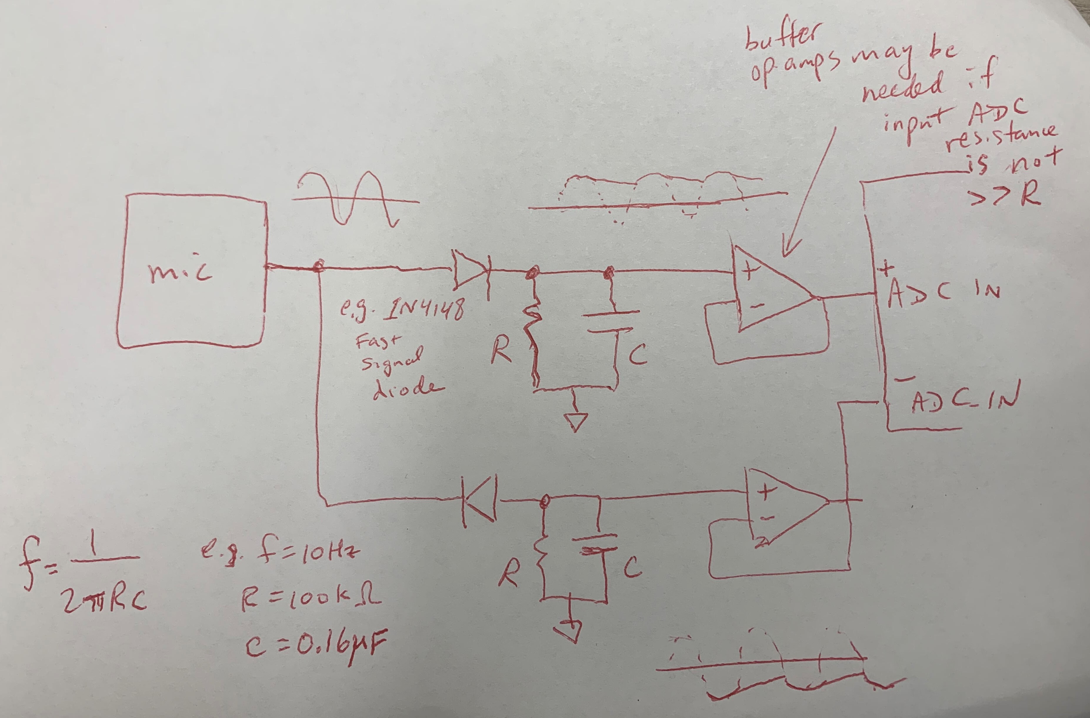
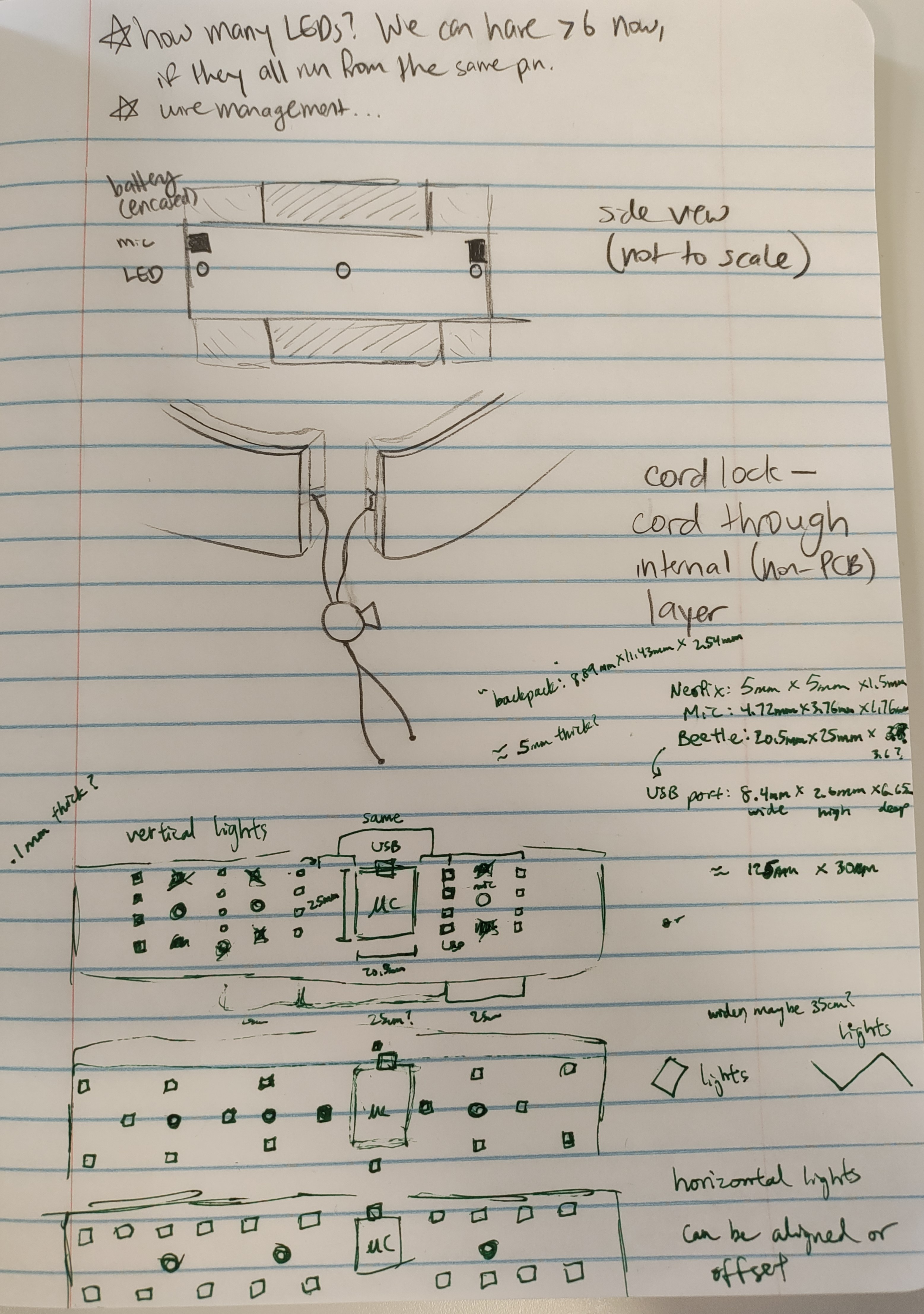
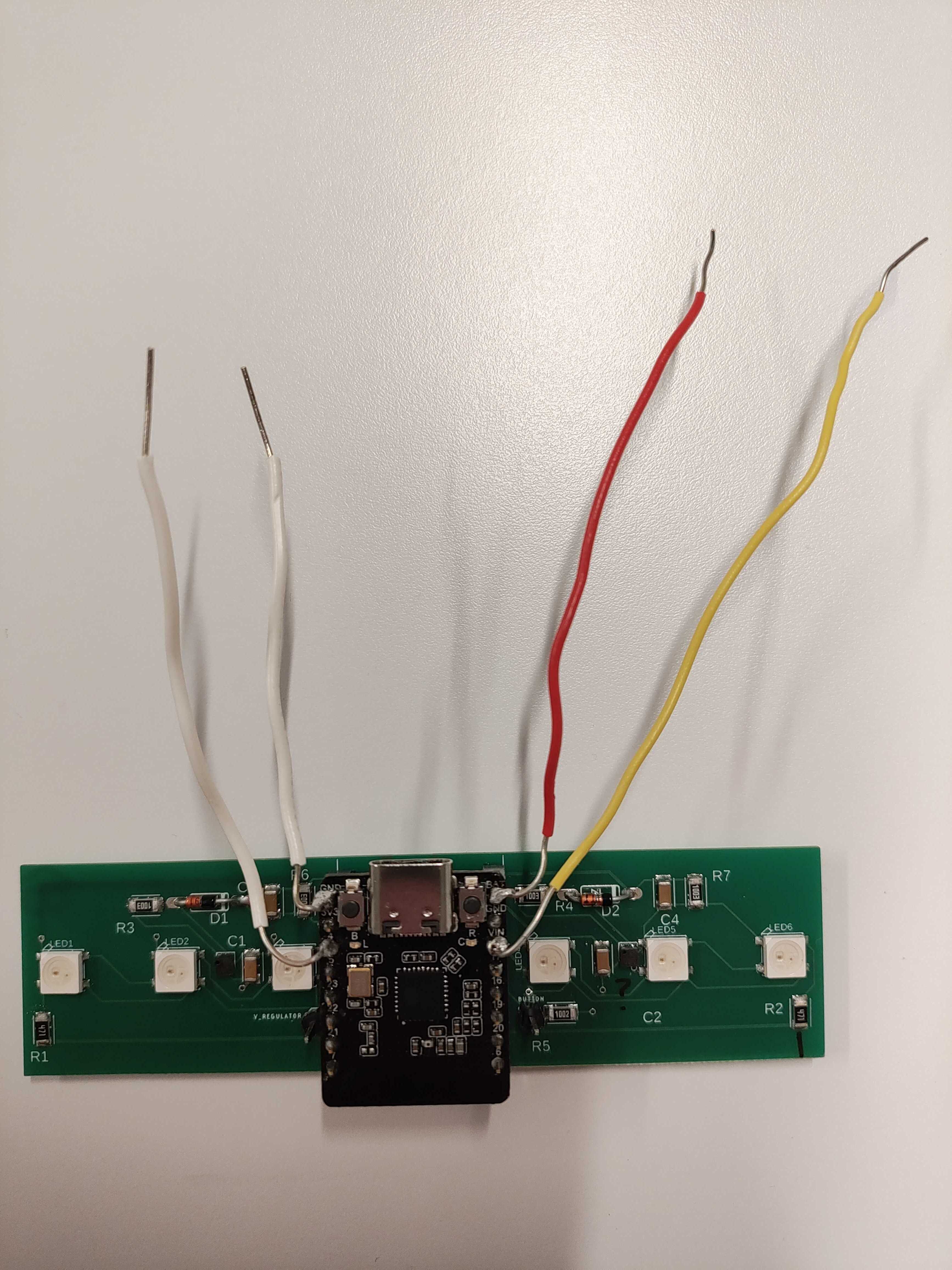
We have legit mic output now, huzzah! It turns out that we needed to solder pins to the Beetle and use a socket to connect the Beetle to the board. Now that the connection is secure, we have realized two things:

  1. The connection wasn’t secure before, and the mic output from before might not have been meaningful.
  2. The mic does in fact respond proportionally to output. The variance can be improved by using a higher resistance value… well, we thought so. It doesn’t significantly improve past a certain point.

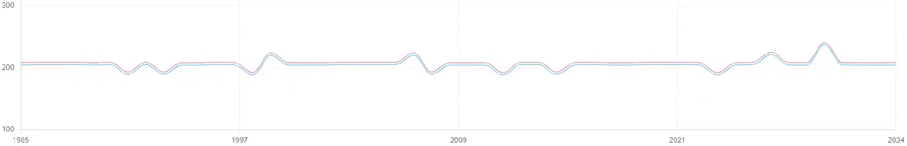
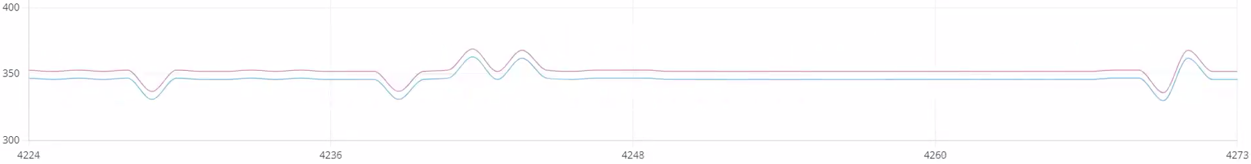
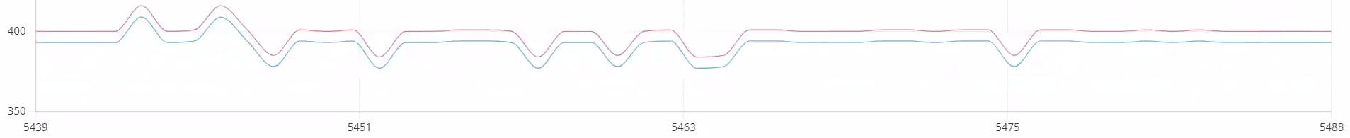
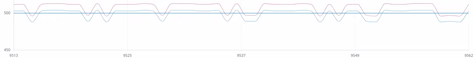
Music studio updates: from testing during one session, we note that the system can pick up on some sounds. The baseline output value seems to drift higher over time. Over the time of 2 songs in the music studio, the input from the tested mic varied within a song by as much as 150 mV. The first song began at approximately 200 mV and ended at approx. 350 mV. The second song began at approximately 400 mV and ended at approximately 500 mV. This effect could possibly be mitigated by introducing calibration.

Beginning of 1
End of 1
Beginning of 2
End of 2

We tested a large range of resistor values, including those greater than the 33k max recommended, in hopes of getting better sensitivity. We tested 50k, 100k, and 200k. The resistance of 200K and 50k were not significantly better/different than 10k. Thus 100K resistors will be used on the new boards since we did have promising potential with those.

This video shows a plot of the mic (above) and peak detector (below) output values as the system responds to music with voice and percussion, using the 100K mic resistor.

https://youtu.be/_pMX454oqqs 

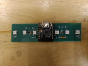
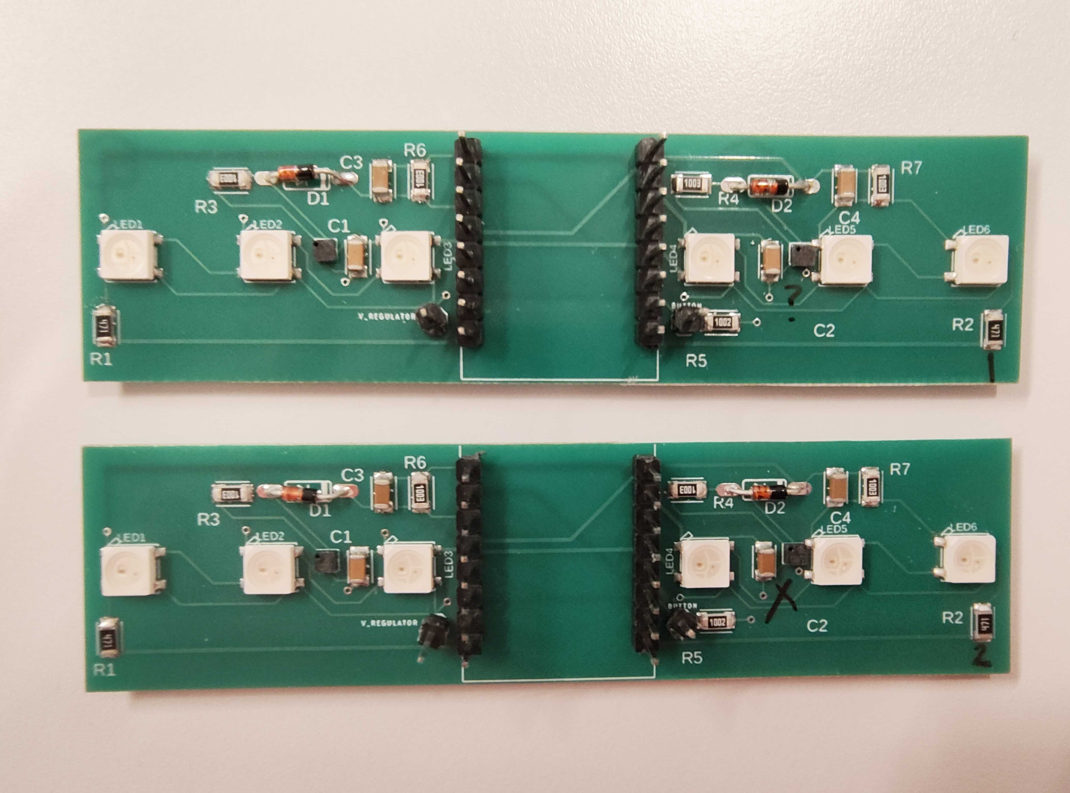
Freda and Lucy also assembled 2 new boards successfully.

What are the most significant risks that could jeopardize the success of the project? How are these risks being managed? What contingency plans are ready?

Significant risks include:

  • Us not getting the new batteries (Katherine ordered the wrong battery size). This messes with the size requirements we have (although not significantly), and we can still use the batteries we have (and batteries of the correct size have been ordered).
  • Something going wrong with BLE. Lucy is planning to meet with a person from another group who has experience in order to understand how to get BLE to work. Another risk is that the BLE connection is too slow (can’t match 1-second speed requirement). In that case, we would want to look into strategies to make the code (either bracelet or webapp) create faster results.
  • Assembly issues. Our contingency plan is to make several copies of the final PCB, both rigid and flex, and to keep the original PCBs as emergency backups.
  • The Beetle randomly freezes. Is it possible that it is going into deep sleep mode? The plan is to research deep sleep mode and make sure that the Beetle does not go to sleep for the duration of its usage.
  • Microphone drifts. While the contingency plan is to calibrate microphone outputs at the start of each session, it would be nice to know what’s causing the drift in the first place.

Were any changes made to the existing design of the system (requirements, block diagram, system spec, etc)? Why was this change necessary, what costs does the change incur, and how will these costs be mitigated going forward?

We are no longer doing directionality: the mic location on either side of the Beetle is not different enough to matter. Also, it is hard to solder mics, so it is rare that both L and R mics work for the same board.

When testing the Beetle on the battery, there is not always a response if battery direct output is plugged into BAT, but it will respond if boosted 5V output plugged into VIN (rated for 5V).

It is possible that the system might require start-up time for mic outputs to settle. The mic datasheet says start-up time for a mic is max. 800 ms, but the peak detector at its output might change things.

Provide an updated schedule if changes have occurred.

There are no updates to the schedule. Everything has to be done by the 30th still.

List all unit tests and overall system test carried out for experimentation of the system. List any findings and design changes made from your analysis of test results and other data obtained from the experimentation.

We unit tested the button, lights and mics. Button and lights work fine. As you could probably guess, we’re still having mic issues.

Remaining tests include comparing decibel meter output to system output, as well as evaluating other qualities of the complete system: weight, adjustability, thickness, durability, timeliness, battery life (to be calculated using data from the battery’s output current), and operating temperature.

It may be concluded from our previous remarks that the system test has failed. We are in the process of asking Erin and Prof. Fedder for help.

Team Status Report for 4/20

This week, we reported on our progress to the music studio in our final visit. We have emailed asking for another session on Thursday or Friday, to hopefully test our final bracelet with calibrated mic values as well as casing.

We started committing by soldering components, which helped determine resistor values so we can switch to SMD to save space. The peak detector circuit is implemented on final (flex) PCBs, and expected to arrive this coming week. We also ordered hard PCBs as a backup in case soldering a flimsy surface goes wrong. All parts for PCB assembly have been acquired.

Our remaining tasks include: BLE, final code for Beetle, mic stuff, and building the bracelet.

For BLE, relating to web apps: we’re using ble-manager instead of ble-plx to connect with the Beetle, and still working on connection and backend. The Beetle is a peripheral for the purpose of the BLE connection.

The final code for the Beetle should include everything we’ve been working on: mic signal processing, LED commands, button input, etc.

Mic signal processing continues. Peak detector values are definitely better, since the peak detector filters out the weird wave pattern we noticed with the previous mic input. One potential issue is that the peak detector output seems to occur in “levels”– almost like high/low values. In order to use this output to command the LEDs, we need to adjust the (one) threshold to be between these two values.

Here’s a video: https://youtu.be/tRXVAB-vj1g

Sorry about the camera quality, but the top 2 moving lines (yellow and gray) represent the values using peak detector, while the bottom 2 moving lines (red and blue) represent values without using the peak detector. As you can see, there are times when the bottom 2 lines are just flat, but the top 2 lines can detect a change, which is promising. The range of values isn’t very large, but could probably fixed with calibration.

In building the bracelet, it was discovered that the pipe from McMaster-Carr didn’t suit our purposes, so we gave it away. We are using multiple overlapping pieces of plastic now.

One remaining issue is that our button doesn’t work. Using the Arduino example code and setup for buttons, we found that the button being pressed does not register. We hypothesize that it might be the Beetle doing internal pull up or down resistors, which messes up the reading because it’s always reading as “off”. One option is to use the example GPIO code for the ESP32, which uses a different method of setting up the button. A back up option exists: we have a header pin, so we can manually reroute to another Beetle pin if necessary if another pin ends up working.

Another remaining issue is that our battery connections are soldered decently but still don’t power the board. As long as this is true, we can’t test the switch for on/off. The cause needs further investigation, but it could be a bad cable.

Our schedule has been updated. The system needs to be functional by 4/24, because that is the day before the first possible day for testing in a music session.

Team Status Report for 4/6

What are the most significant risks that could jeopardize the success of the project? How are these risks being managed? What contingency plans are ready?

The most significant risk is that we do not finish in time. As of the interim demo, web app progress is proceeding well, but hardware is somewhat behind where we expected to be; for example, microphone signal processing is taking much longer than anticipated. This risk is being managed by trying to do tasks that require significant waiting (like ordering parts or PCBs) as soon as possible, and by having multiple versions of the PCB to test with.

The second most significant risk is that the microphone output does not correctly connect to the PCB ADC input, making it impossible to extract meaningful data from the microphone values. This is being managed by implementing a peak detector circuit between the microphone and ADC on one of the final board designs. If this issue is due to loose connections, then the original design on flexPCB will work as expected once everything is soldered together; if this issue is due to some fundamental problem with the mic-PCB relationship, then the peak detector circuit will resolve it. If this is an assembly issue due to how tiny the mic is and how difficult it is to solder precisely, making many boards will help solve it by increasing the expected value that at least one board will end up with working components.

This is Prof. Fedder’s sketch of how the peak detector circuit should be included in the overall design.

Were any changes made to the existing design of the system (requirements, block diagram, system spec, etc)? Why was this change necessary, what costs does the change incur, and how will these costs be mitigated going forward?

Changes were made to the block diagram: for one version of the final design, a peak detector circuit (composed of 2 resistors, 2 capacitors, 2 op-amps, and 2 diodes) now exists between each mic output and microcontroller ADC input.

Provide an updated schedule if changes have occurred.

All code, assembly, and testing must now take place before April 21st. The flexPCBs will be ordered this week.

Now that you have some portions of your project built, and entering into the verification and validation phase of your project, provide a comprehensive update on what tests you have run or are planning to run. In particular, how will you analyze the anticipated measured results to verify your contribution to the project meets the engineering design requirements or the use case requirements? Verification is usually related to your own subsystem and is likely to be discussed in your individual reports. Validation is usually related to your overall project and is likely to be discussed in your team reports.

We have not yet run any of the tests under the explicit rules stated in the design review, because they require either a complete bracelet or a complete mic-LED system. Since the results of each test are directly related to the requirements, considering which requirement is fulfilled by passing each test (with reference to the chart in the design review) should suffice.

Team Status Report for 3/30

Currently, the greatest risk is that we will not be able to extract usable data from the microphones. If this is because the microphone doesn’t react to any sound input as proven on the oscilloscope (likely incorrectly soldered), we can repeat the assembly/soldering process with more components. If the microphone reacts to oscilloscope testing but not to the microphone testing program that prints to the serial monitor, further microphone testing is required to determine the source of the issue. If the microphone reacts to environment sound but the data we receive does not directly correspond to what we expect, we need to continue signal processing to calibrate the data.

We need to have the hardware aspects mostly complete by Tuesday (the first music testing session of the week) and the webapp subsystem mostly complete by Wednesday (interim demo day).

Since last time, we tested the microphones and LEDs on each board to find out which boards have which functioning. We also tested a program that would change the LED color if the microphone input exceeded a certain threshold. Webapp research about the database and file format continues. Also, we now have a decibel meter! This will provide a baseline against which we can measure the bracelet results.

We haven’t changed the design of the system.

The Gantt chart has been updated:

  • The interim demo is now scheduled for Wednesday, April 3rd.
  • Database, visualization, customization is due Friday, April 6th.
  • Timeliness/accuracy/heat tests are also due April 6th.

Clapping demo

Caption: The lights change color to red and back to yellow very fast, so if you want to see it better, change the video speed to 0.25, and focus on 0:02 to 0:04.

Also available on YouTube: https://youtube.com/shorts/fKVRntFnD_Q

Team Status Report for 3/23

This week, we received and put together the PCB prototypes, started code for the bracelet, and worked on the webapp.

  • What are the most significant risks that could jeopardize the success of the project? How are these risks being managed? What contingency plans are ready?

One risk is that the plastic wrap still hasn’t come in, so the interim demo bracelet might need to be fabricated entirely out of plastic tubing or have no plastic covering. The casing isn’t a major subsystem, so we should be fine without casing for the interim demo anyways. BLE setup/interfacing is also challenging, but will be addressed after the interim demo when integrating the bracelet and web app.

  • Were any changes made to the existing design of the system (requirements, block diagram, system spec, etc)? Why was this change necessary, what costs does the change incur, and how will these costs be mitigated going forward?

No changes were made to the existing design of the system. Soon after the interim demo, we may consider changing requirements or other design elements if feedback suggests that it would benefit the system.

  • Provide an updated schedule if changes have occurred.

The Gantt chart has been updated to reflect that complete (separate) subsystems of the physical bracelet and webapp are due April 1st (interim demo).

  • This is also the place to put some photos of your progress or to brag about a component you got working.

Isn’t it beautiful? Let’s hope it actually works.

Team Status Report for 3/16

General updates

Due to significant differences in different sound apps reading the same sound, we decided to narrow down the variables involved by all downloading the same app and placing votes as close together as possible. We still get different dBs for the same app, but we also have different phones/mics, which we can’t control. The standard deviation between us is about 3 to 4 dB, which is outside of our desired range of being within 2dB of accuracy. The problem is, we don’t even know who is the most accurate, only that we are precise. Luckily, Prof Sullivan offered to give us a more trustworthy decibel meter starting the week after next, which can hopefully clear up this debate permanently. We will be taking it to practice sessions with the music students that we have been coordinating times with.

We also discussed microphone signal processing in our weekly meeting with Prof Fedder. Since microphone noise is negligible compared to the loudness we’re measuring, and we’re only interested in measuring loudness, filtering out noise probably isn’t necessary. A basic version of mic signal processing would measure the amplitude of the incoming signal a certain number of times per second and linearly scale that to dB levels. A more sophisticated version would use an FFT (https://projecthub.arduino.cc/abhilashpatel121/easyfft-fast-fourier-transform-fft-for-arduino-03724d) to see the “spikes” within the frequency range we are interested in, and take the maximum of the spike amplitudes. The problem with either version is that in order to account for frequency overtones and Nyquist’s theorem, we need to sample thousands of times per second. This might be computationally expensive.

What are the most significant risks that could jeopardize the success of the project? How are these risks being managed? What contingency plans are ready?

The PCB doesn’t get here on time (expected arrival Tuesday). Given how much this delay has blocked our progress this first iteration, when we order the final (flex) PCB, we plan to pay extra for fast shipping instead of regular shipping, since we have enough left in our budget.

Were any changes made to the existing design of the system (requirements, block diagram, system spec, etc)? Why was this change necessary, what costs does the change incur, and how will these costs be mitigated going forward?

No changes were made to the existing design. We’re still planning to order a flex PCB with the final design once we have tested the rigid prototype PCB and noted what changes need to be made.

Provide an updated schedule if changes have occurred.

The schedule has been updated. PCB creation/delivery took longer than expected, and a lot of tasks depend on us having the PCB, since a lot of the components are tiny SMD things that we can’t try to do by hand.

This is also the place to put some photos of your progress or to brag about a component you got working.

Here is a picture of the stencil for our PCB.

A tilted view of the PCB stencil in light blue.

Gantt Chart changes:

Software: Due to difficulties in getting the Bluetooth connection to work on the mobile app, we have allocated an extra half a week to figuring it out. Additionally, the decibel reading display and visualization algorithms have been moved forward so that they can be done by the interim demo (4/1). Since full integration of the bracelet and the web app won’t occur until after the interim demo, these pages will be displaying information using dummy data.

Hardware: Electronic prototyping/PCB assembly and microphone signal processing have been moved forward by a half-week as well, because we can’t do much without the PCB being physically here.

Team Status Report for 3/9

Last week’s focus was completing the design report. It has been uploaded to this site.

This week’s focus was creating the PCB design and ordering the PCB. The circuit diagram needed to be converted into a schematic for neatness. The circuit block diagram has changed during the PCB design process. The LED array now has start/end resistors, as indicated on page 10 of the SKC6812RV datasheet included in the Neopixel listing on Adafruit; capacitors are included, to decrease noise from power; and the mode control button now uses a pulldown resistor.

More parts have arrived; currently, the only missing parts are the plastic wrap, cord locks, and PCB. The PCB should arrive sometime this week, after which the electronic components can be attached and electronic prototyping can start.

One risk is schedule changes making it difficult to complete one working subsystem before the interim demo on April 1st. Certain tasks require previous tasks to be completed (for example, connecting Bluetooth to the web app requires establishing a secure Bluetooth connection on the Beetle), and we updated our Gantt chart to acknowledge that some future tasks (ex. Bluetooth-webapp connection) need to be pushed forward a week so that we can finish the tasks that they depend on (ex. Bluetooth connection setup in electronic prototyping). However, since we still have buffer time at the end of the chart, this is not as much of a concern as it could be. Our goal for the interim demo is that by working on the web app and bracelet in parallel, we’ll have at least one of those major subsystems done in time, even if they don’t talk to each other.

Survey feedback indicated that users would want a small, thin bracelet with a shorter (4-6 hour) battery life (as opposed to either a wide & thin or a small & thick bracelet with the original 8-hour battery life).

We have also decided to use exclusively plastic wrap for the exterior of the bracelet, since it comes the closest to meeting the sizing requirements when thicker plastic tubing is not used.

Finally, our schedule has been updated; the Gantt chart can be found here.

A screenshot of our Gantt chart

A) Global Factors [Lucy]:

Globally, hearing loss is one of the most prevalent disorders and is expected to rise by over 60% in the next few decades [1].  Our bracelet will serve as an easy and convenient way for people to check their sound levels. The bracelet is designed to be comfortable, durable, and practical to use for anyone that wants to be more aware of their surrounding noise levels. While our current use case is musicians, the bracelet is not limited to people in the music field. Anyone around the world that has a device that connects to bluetooth will be able to benefit from our product. The web application also is simple and easy to use. Even those who are not technologically savvy will be able to easily navigate through the user friendly interface to observe their sound level readings.

  1. https://www.ncoa.org/adviser/hearing-aids/hearing-loss-statistics/#rates-by-age

B) Cultural Factors [Katherine]:

In many locations, cultural traditions and practices include musical education and performance. In order to ensure that these musical traditions continue, it is important to take steps to increase participant safety. Our project, which will provide easily-understandable visual feedback for awareness of participants’ sound environments, would allow participants to make more informed choices about their noise exposure levels (for example, practice time duration and frequency). This should allow them to continue safely interacting with music over longer timespans, allowing them to continue the musical traditions of their communities.

Considerations of beliefs and moral values do not apply to this product, because it only provides information to the user and does not suggest what actions they should take as a result. Language considerations apply to our project because the language used in the webapp needs to be both easy for the user to understand and scientifically accurate; in addition, text content should be in a language that users understand.

Laws are relevant to our product, including those regarding wireless transmission (since we are using a premade Bluetooth module, this consideration is taken care of by the creator). Also, even though our project should not and will not save audio data, the presence of microphones means that we should keep in mind laws about privacy. Someone could hack the bracelet and try to use it to illegally record conversations (Pennsylvania is a two-party consent state for recordings, as stated in https://www.dmlp.org/legal-guide/pennsylvania/pennsylvania-recording-law). For that reason, when developing this device, we need to make sure that the microphone data is only ever used to generate decibel values and cannot be used to record or save audio files.

C) Environmental Factors [Freda]

We predict that our device won’t have much effect on the environment. The materials used aren’t renewable or biodegradable, but then again what electronic components are? We decided on plastic casing because of its durable and clear qualities, which not many other materials we know of have (that are also readily available). Thus, we intend for our product to last a long time to help mitigate the pollution cost of materials, as well as advise users to dispose of e-waste properly (not with the regular trash).

In terms of specific living organisms affected, we don’t think the lights would be so bright as to blind others (and the lighting is also adjustable), so animals shouldn’t be harmed, and not sure how plants would be harmed either since they don’t really have eyes. (On the flip side, the lights are probably not bright enough to be used to keep your plants alive, either.) The most danger that animals could run into from this is if the user’s pet(s) decide to eat it, which is something that pet owners should already be aware of (since they have many other items that they don’t want eaten either), so keeping this bracelet safe requires no mitigation out of the usual measures.

Team Status Report for 2/24

What are the most significant risks that could jeopardize the success of the project? How are these risks being managed? What contingency plans are ready?

Unfortunately, our size requirements are most threatened by the battery size, because everything else can be quite small. Unfortunately, small and powerful batteries are presumably not on the market for proprietary reasons, so we can only have big bulky batteries. The battery we currently have will last for about 8 hours, which is the max time that one of our surveyed users wanted it to last for. Unfortunately, that means it must be bulky, either in the width or height direction. We are debating how necessary it is to cater to the person with the max time requirements, or whether we should focus on the lower time that the majority of the respondents stated, which is up to 4 hours straight. This would allow us to use lighter and smaller batteries, which would be more comfortable for the user. Thus, we will be asking our target demographic about these tradeoff decisions and what they would most prefer when we meet them on Monday.

As another option, we were also considering whether users could be able to swap out the size of the battery being used to fit their use requirements. Unfortunately that would add more designing of the battery pouch to make it fit both options (otherwise a smaller battery in a large bag wouldn’t save any space), and we’re not sure if this is something that’s really crucial.

Were any changes made to the existing design of the system (requirements, block diagram, system spec, etc)? Why was this change necessary, what costs does the change incur, and how will these costs be mitigated going forward?

The width requirement was returned in response to feedback in the design review Q&A, and modified to 70 mm to match the estimated width of the current design of our bracelet. This does not incur any specific cost at the moment; however, it might make the bracelet less comfortable for users. This potential cost will be identified if it exists through the planned integration test, and will be mitigated by rearranging the parts to create a bracelet with a width smaller than 70 mm.

Right now, the design only has one battery (because calculations showed that the bracelet might be able to meet the battery life specifications with only one battery) and two microphones (because there are only two Arduino digital input pins on the Beetle). A possible cost of using only one battery is that, if the components pull more current than expected, the battery life will not meet requirements. In that case, we would consult with staff to choose an alternate battery configuration that meets our requirements. A possible cost of using only two microphones is that there are fewer chances to correct errors; if one microphone’s input is incorrect, it has a greater effect on the overall calculation. We can mitigate this by processing microphone input in the code that converts microphone inputs to dB values.

Provide an updated schedule if changes have occurred.

The Gantt chart was updated; the most significant change is deleting a double-count of Bluetooth setup in both the hardware and software sections. We have extended some end dates for tasks, but the final parts of the project (integration and testing) have the same start/end dates, so the project remains on schedule overall.

Team Status Report for 2/17

This week, we worked on finalizing design choices in preparation for the design review next week. We also attended Professor Dueck’s class, where we could collect some preliminary data points for dB, check out some of the different rooms available, and ask for user feedback of what kind of product they’d prefer.

What are the most significant risks that could jeopardize the success of the project? How are these risks being managed? What contingency plans are ready?

One of the most significant risks we identified today is the possibility that the sizes of the materials we have chosen make it impossible to meet the sizing requirements we have set. We are managing this risk by relaxing our sizing requirements. We are also trying different prototyping methods that still try to minimize size as much as possible.

Were any changes made to the existing design of the system (requirements, block diagram, system spec, etc)? Why was this change necessary, what costs does the change incur, and how will these costs be mitigated going forward?

We have created a battery life requirement of 8 hours, which is the maximum amount of music-interaction time without a break that was brought up in conversation with participants in the music studio.  That creates the need for these relatively large batteries.

We are eliminating our thickness requirement. When considering preliminary sizing, we realized that the given dimensions of the parts we have agreed on (battery, microcontroller, LEDs, microphones, and boost converter) would not be feasible given the thickness and height requirements we had created. From there, we had a choice of eliminating the height requirement (creating a chunky bracelet) or the thickness requirement (creating a cuff/armband style of bracelet). We chose to eliminate the thickness requirement because eliminating the height requirement would make the bracelet stick out too much to be comfortable to wear (and would also make it more prone to damage). One concern with this solution is that it could interfere with wrist movements; given that our potential users include pianists, this is an important concern. We decided that the bracelet should be adjusted to be worn sufficiently far back that it does not cover the wrist or interfere with wrist movement. We will still attempt to minimize thickness, and rely on user feedback to determine if this is a satisfactory solution.

In our weekly meeting, we confirmed that connecting our components via a PCB is necessary. The alternative had been to individually solder/wire each component together, but this is probably impossible because of the size of the components. We are going to connect all non-battery components together on a flex PCB, and include a place to plug in the battery. This results in an increased cost for our system (from ordering the custom PCB).

Also in our weekly meeting, we discussed the idea of using 2 small batteries (instead of 1 large one); the battery life requirement dictates that we use larger batteries, but maintaining a relatively small size is important. Our plan is to use 2 small batteries, one on either “side” (above or below the wrist) of the bracelet, and have them wired in series to provide one red/black battery connection to the PCB. The risk is that, if done incorrectly, this can ruin both batteries; however, we are going to verify that our plan is safe before carrying it out, and take safety precautions while wiring the batteries together. In addition, if we test the bracelet and discover it uses less power than we thought, it’s probably easier to decrease the number of batteries than to increase it retroactively.

Provide an updated schedule if changes have occurred.

We have pushed forward tasks related to materials to account for the delay in finalizing and therefore in ordering materials. The tasks covering finalizing materials, ordering and receiving parts, electronic prototyping, Arduino-Bluetooth connection, LED signal setup, and the Bluetooth-webapp connection have all been moved forward to the week of February 25th. Also, software task deadlines have been moved forward because it took some time to get familiar with React Native; therefore, the deadlines have been moved to the 23rd and 25th, respectively.

This is also the place to put some photos of your progress or to brag about a component you got working.

Here are some sketches of our physical design.

A sketch of the bracelet with the outer layer labeled "plastic tubing" and the inner layer labeled "wire wrapped w/ string". A battery connection to the PCB is indicated. A stopper made of laser-cut acrylic is at each end of the plastic tubing.

Three side-views of the bracelet. One has vertical lights in line with the mics, one forms a diamond of lights around each mic, and one has horizontal lights which can be aligned or offset from the mic. Notes estimate component sizes, and show that lights can be arranged in a zigzag pattern.

How will our product meet a specified need…

with respect to public health, safety, or welfare? [Freda]

As mentioned in our introduction page, hearing loss was the leading sensory disorder in the US. Other than obvious uses such as listening to music and friends, our ears are also important to help with balancing, and even mild hearing loss doubles the risk of dementia [1]. In addition, people may not be as good at accurately interpreting the “loudness” of sound vs the actual decibel value, due to our ears being more sensitive to certain frequencies [2]. An objective way of measuring decibel levels, such as a phone app, would be nice, but inconvenient to pull out every time you want to check. Thus, a wearable device such as a bracelet would be a helpful way to monitor volume continuously throughout the day. This can be useful for musicians or other workers in loud environments, or anyone who wants to be more mindful of their surroundings. Once people are more aware of potential risks, they can take steps to mitigate and protect their hearing preemptively.

[1] The Hidden Risks of Hearing Loss | Johns Hopkins Medicine

[2] Equal-loudness contour – Wikipedia

with respect to social factors? [Lucy]

Our bracelet meets social needs by providing a convenient method for users to be more aware of their overall sound surroundings. With the adjustable light and color customization, our goal is to offer a product that caters to a diverse set of users, extending beyond those with full sight. Individuals with disabilities, like colorblindness, can also fully use our bracelet by customizing the colors to best suit their needs and preferences. Additionally, in settings where bright, flashing lights may be inappropriate, the bracelet can be customized to emit a softer glow. The light intensity can easily be adjusted to suit whatever the current social setting is.

with respect to economic factors? [Katherine]

The bracelet-webapp system is not meant to replace existing decibel meters and apps; therefore, it should have no effect on the production and distribution of these goods. While its goal is to create mindfulness of sound levels, the overall effect of this mindfulness remains to be seen. It is possible that increased mindfulness leads to users producing or consuming less music, because they are limiting their exposure. However, it is also possible that increased mindfulness will give users a better knowledge of when to take breaks, letting them engage with more music and therefore increasing their overall production and consumption.

Team Status Report for 2/10

Summary of Accomplishments

This week, we presented our proposal and received feedback from faculty. Here are our thoughts:

  • Robustness of the audio system is a good idea: we need to factor in making our data collection more robust to “noisy”/bad data.
  • In average mode, the average incorporates data gathered since the beginning of the session.
  • The intended device use time = 8 hours before recharging, since that’s about how long Professor Dueck says people work for.
  • The timespan of instantaneous = 1 second (response time goal).
  • Bracelet networking is an interesting idea, but we envision our device as an individual solution.
  • Directionality will be incorporated. With multiple microphones, data about varying sound levels in different directions can be gathered.

We also met with Professor Dueck, Assistant Professor for Collaborative Piano and Vocal Coaching, whom we are collaborating with for our project. She introduced some use cases, such as how some practice rooms they were given weren’t designed with acoustics in mind so they weren’t very comfortable to use, or how orchestral musicians are concerned for their hearing because they are surrounded by loud instruments but still have to hear details in the music. We are looking forward to meeting with her and her students on Monday so we can interview more potential users to better understand what features would be most beneficial for them and what else we can improve for our design.

What are the most significant risks that could jeopardize the success of the project? How are these risks being managed? What contingency plans are ready?

Currently, the most significant risk we foresee is that parts will be damaged in the fabrication or testing processes. To mitigate this risk, we intend to order multiple copies of electronic components (5+ of each?).

Were any changes made to the existing design of the system (requirements, block diagram, system spec, etc)? Why was this change necessary, what costs does the change incur, and how will these costs be mitigated going forward?

Firebase will no longer be used; its purpose can be fulfilled by Django. The LED strip choice was changed to Neopixels, because it runs on a lower current, so our battery can last longer. The design now has a specific choice for microcontroller: the Beetle ESP32 C6 Mini Development Board, for its BLE capability, small size, and safety (wearable safety is not explicitly stated, but two of the applications on the store website are wearable devices). Our battery choice is two 3.7V 2000mAh lithium-ion batteries to facilitate a longer use time while still meeting our size requirement. With these components decided, our plan for layout is to have the batteries on the top and bottom of the wrist, with the microcontroller between them on one side, leaving the fastening mechanism on the last “side”. The microphones can be placed about equidistantly around the wrist, so it’s likely they’ll land on top of the batteries/microcontroller area.

Provide an updated schedule if changes have occurred.

The Gantt chart has been updated to reflect that materials were not finalized until 2/10 instead of 2/7. Also, ordering parts will begin on 2/12 instead of 2/8.