Bethel’s Status Report for 3/18/2023

What did you personally accomplish this week on the project? Give files or photos that demonstrate your progress. Prove to the reader that you put sufficient effort into the project over the course of the week (12+ hours).  

My team and I brainstormed and compiled a variety of ethical considerations concerning our project in preparation for the ethics lecture and group discussion. 

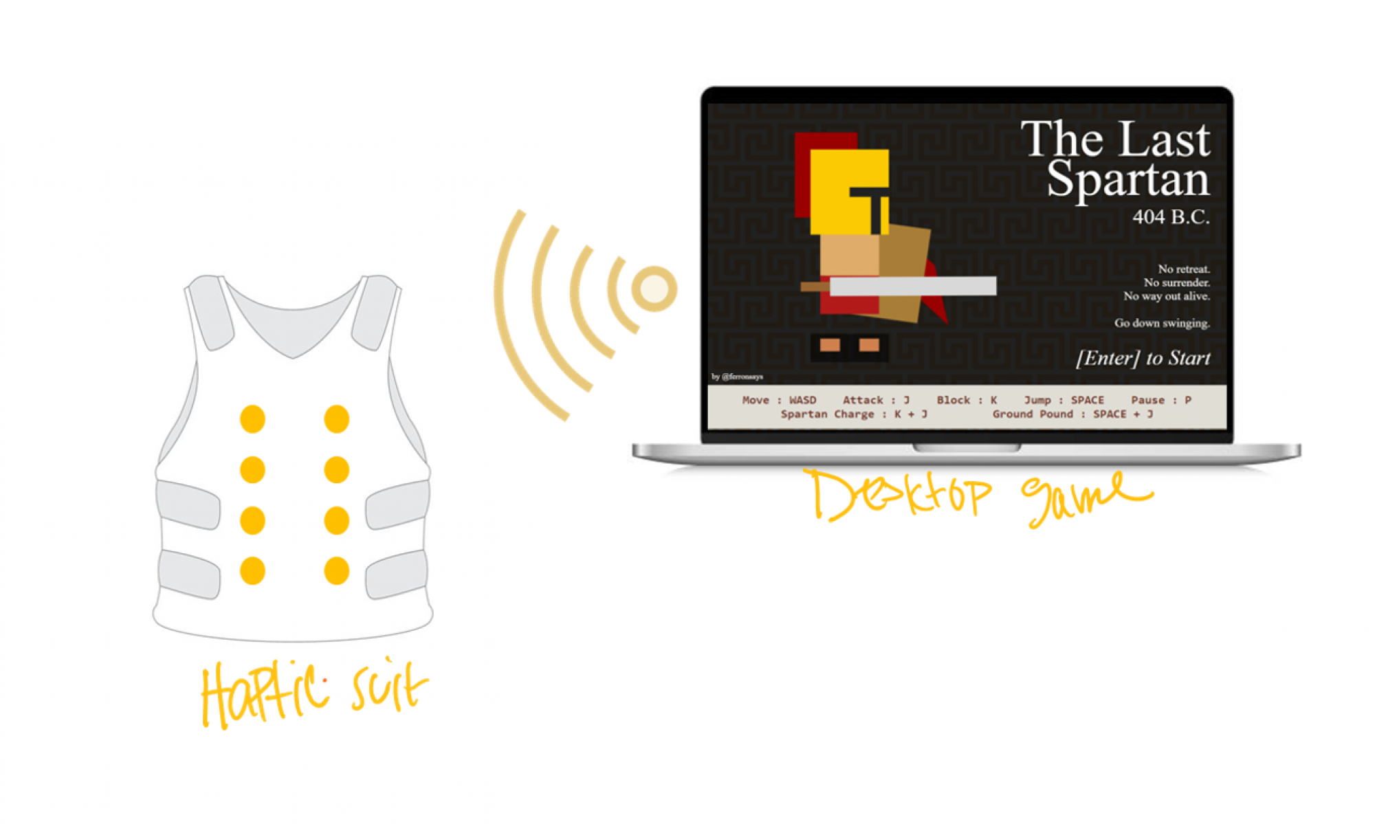
This week I was able to track the forceful jump game event successfully using JavaScript event listeners. I have decided to incorporate a web scraper library known as Puppeteer to aid in tracking the game actions of the remaining three events, namely small hit, large hit and low health. Puppeteer will help me analyze different enemy actions in order to accurately transfer data relevant to the game action taking place. For instance, we would not want a low health event to be flagged every time the life bar decreases, instead we would like this event to be activated when the bar decreases to 25% of its original length. 

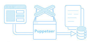
Figure 1. Shows how Puppeteer interacts with the live data inputs coming from the browser which it passes on to our Node JS server.


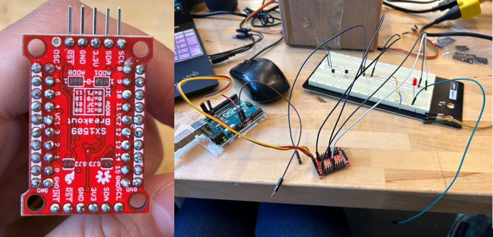
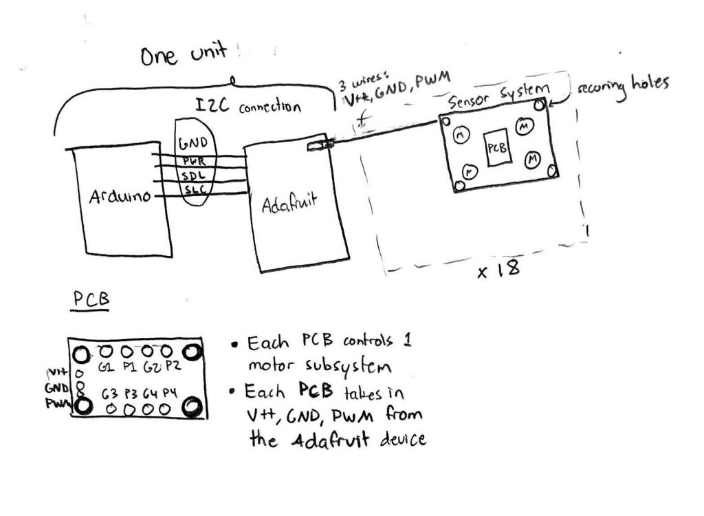
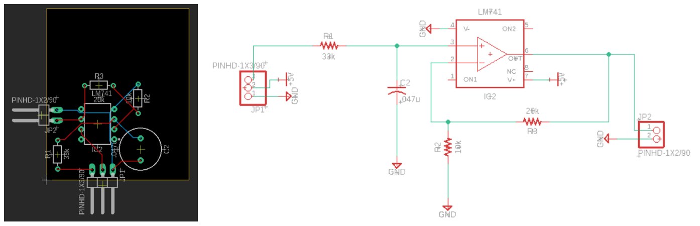
After building the Node JS server last week, I tested my code using a two button webpage, whereby the “Turn Motor On” button represents the activation of a game action and the “Turn Motor Off” button deactivates the motor as shown in Figures 2 & 3. This helps test the proper functionality of the Node JS server while it is in the early development stage. Furthermore, I have designed a single motor circuit using an Arduino Uno as shown in Figure 1. to simplistically mimic the behavior of our system of motors.

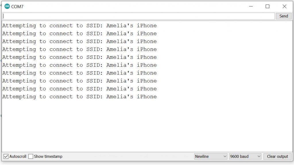
Figure 2. Shows the simple two button webpage I used to test the functionality of my Node JS server.

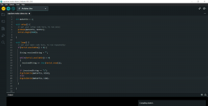
Figure 3. Shows the simple Arduino code I used to test the functionality of my Node JS server.


Is your progress on schedule or behind? If you are behind, what actions will be taken to catch up to the project schedule?  

My progress is somewhat back on track since I have managed to build the Node JS server based on dummy data and successfully track one game action. I still have to integrate the two components together and test them in unison before I proceed. I will also be focusing on how to use Puppeteer to acquire data from all the remaining game actions as well. 


What deliverables do you hope to complete in the next week?

This week I plan to integrate the two components to see whether the Node JS server can relay our game data successfully to our simple motor circuit. Moreover, I plan to test my software on the Arduino WIFI Rev while it is still connected to a PC, before moving on to establishing a wireless connection.


Amelia’s Status Report for 3/18

Updates for the week

This week, I focused on parsing the POST request data from POSTMAN. I got this to work successfully, but after consulting with my teammates Bethel and Sophia about what the incoming data is going to look like, I realized that parsing data from POSTMAN is not the same as parsing data from JSON, but we agreed that any incoming data will have the string format “? MA, LA”

Where MA is a string that holds any of the 5 string values: ”  “, “FJ”, “HS”, “HL”, “LH” corresponding to a motor action (i.e. FJ->Forceful Jump, HS->Hit Small, HL->Hit Large, LH->Low Health). LA holds similar 5 values: ”  “, “W”, ” HS”, “HL”, “W” which corresponds to a light show action (i.e. W-> character in water).

I will parse this string format and hold the corresponding values in a struct so that the motor and light algorithms are able to case on these value instantly and send the correct response to the motors/lights.

These will start with a ‘?’ to let the IDE know we’re receiving the proper data.

Next, I worked on prototyping the actuator mounting board. I started by creating a CAD model with squares and added 2 mounting holes 10mm in diameter to these squares. I laser cut them on (1/32)” cardboard then realized the motor surfaces weren’t flush with the cardboard because they didn’t have a notch for the wires in sticking out of the motors. I then added a notch on CAD and did several iterations of prototyping on cardboard. I laser cut on slightly thicker cardboard but the motor just fell out because the gap couldn’t support the motor, then went back to prototyping on (1/32)” thick cardboard. The image below shows the iterating process. I finally landed on a design which has holes 9.7mm in diameter (slightly smaller to ensure the motor doesn’t fall out) and a gap of 5mm between the two motors. I also tested these at half/full power and it wasn’t unpleasant at 5 mm apart, and did not fall out of the mounting hole.

I also worked on setting up the RGB lights. I turned on 1 LED but need to spend more time on it in order to have the Low Health light show functional as I stated in last week’s status report.

Progress On Schedule

Since I am no longer designing the PCB board, I only have to focus on getting the lights working, the motor mounting plate finalized, and Arduino working wirelessly. I have the Arduino working wirelessly already, it’s just a matter of parsing data from JSON, not from POSTMAN. I’m behind on getting the light algorithm working, so I will spend tomorrow (3/19) working on it.

Deliverables for next week

For the final motor placements, I’m intending on using a different, more durable material. I’m hoping to finalize choosing which material this is going to be, I’m in-between acrylic or a silicone sheet because of its lightweight and heat resistance. I plan on talking with the professor more about the pros/cons of each material.

Once Sophia has the finished dimension for the PCB, I plan on editing the CAD model to make space for the PCB on the actuator mounting board and laser cutting 8 of these to have them ready for the interim demo. The idea is that these 8 will go on the front of the vest, and I will make a plan to mount + wire them on the vest so that they do not move.

I will also get the low health light show algorithm working by the end of the week, so that we are in good standing to have at least one action completely done before the interim demo.


Team Status Report for 3/18/2023

Most Significant Risks

The PCB needs to be designed and simulated before sending the design out for printing. If we don’t get the design sent out soon, this might delay our current plan to have a basic full-system operation working before the interim demo. We are going to manage the risk of not getting it done in time by finishing the design by Monday of next week. This will allow us about one week of printing time and one week to test the full hardware with the PCB. Our interim demo is in 2 weeks, so we hope to have a full system demo for at least one in-game action working by then. Our contingency plan is to have the interim demo with only one motor in each subsystem directly connected to the motor driver. This will allow the users some idea of how the feedback system will work even if it won’t provide the amount of feedback we plan to have for the final. 

Changes to Existing Design

Upon consulting with Omkar and Professor Gary Fedder, we have decided to completely abandon the game code translation process. Instead we will be going back to the original strategy of using JavaScript event listeners to track different game actions. This changes our software design in that we will be using socket.io to relay information to the Node JS server and the server will then use the serial port package to send this information to our Arduino. This change was necessary because limited progress was made in transferring the AI component of the game code from Javascript, HTML and CSS to Node JS.

Additionally, we previously had differing ideas on how the PCB would be mounted and connect to the motors, but upon our meeting with Professor Gary and Omkar this week, we decided that the motors should be mounted separately, and the PCB should be attached to the motor mounting plate instead of it being one entire system. This will make our design more modular to changes since it’s easier to laser cut a new mounting plate than it is to design a new PCB if we want to make slight changes to the motor positions. 

Updated Schedule

N/A. Somehow, we’re not off schedule yet. 

Sophia’s Status Report for 3/18/2023

Accomplishments this week

This week I tested out a different option for our I2C motor system driver. The new board I tested was the SparkFun 16 Output I/O Expander Breakout – SX1509. The voltage level and current were lower than the Adafruit servo driver, but this board only needed two wires to run a PWM device. However, through testing, I found that the Adafruit device provided a better option as a motor system driver. 

Figure 1: Sparkfun device soldering and testing

After deciding on a motor system driver, I was finally able to begin a PCB design which would take the PWM signal, V+, and GND from each motor driver output of the Adafruit device and transform that PWM into a voltage level to drive each motor in the motor system. In the original drawing, the plan was to have up to 4 outputs for the possible 4 motors each motor system would run. Amelia then brought up that we might be able to get around this by soldering the ends of the motors together so the PCB would only need one variable V+ output and GND output for the motors. The final design will have the Arduino and Adafruit device close together on the vest. Because these two devices take up the most room (header pins facing outwards), this will limit the bulkiness in the overall vest design. There will then be 16 sets of PWM, V+, GND pins coming out of the Adafruit device going to 16 of the 18 motor subsystems.

Figure 2: Hardware diagram with PCB and motor system

I found a basic PWM to DC voltage conversion online (https://www.egr.msu.edu/classes/ece480/capstone/spring15/group10/Application%20Notes/Kyle.pdf) and began to implement it in Fusion 360 to get a feeling for the tool. I was able to implement the design and discuss with Amelia what the best layout for the PCB would be. 

Figure 3: Testing out opamp circuit on Fusion360

Schedule update

On Sunday, I plan to do some circuit analysis on the current PWM to DC voltage converter. I plan to research which opamp will fit the project the best and go through the problem to figure out the other parts we should need. I will also continue to work on the motor code which I deviated from this week in order to focus on the PCB design. 

Deliverables for next week

I hope to check with Professor Fedder and Omkar on the PCB design before sending out an order. I will then have to go onto DigiKey or a similar website to order the opamps, resistors, capacitors, and other components for the PCB. 

Bethel’s Status Report for 3/11/2023

What did you personally accomplish this week on the project? Give files or photos that demonstrate your progress. Prove to the reader that you put sufficient effort into the project over the course of the week (12+ hours).  

Considering the little progress I made in transferring the AI aspect of the game code from Javascript, HTML and CSS to Node JS, and having communicated these issues with Professor Gary Fedder and Omkar, I have decided to completely abandon the game code translation process. Instead I will be going back to the original strategy of using JavaScript event listeners to track different game actions. 


I have also managed to build the Node JS server that will be relaying the game data to our Arduino IDE. The Node JS server is currently being triggered using a single button that represents a game action. This helps test the proper functionality of the Node JS server while it is in the early development stage. Furthermore, I have designed a single motor circuit using an Arduino Uno as shown in Figure 1. to simplistically mimic the behavior of our system of motors.


Is your progress on schedule or behind? If you are behind, what actions will be taken to catch up to the project schedule?  

My progress is somewhat back on track since I have chosen to proceed with creating the Node JS server prior to the plan within our schedule. I will therefore, use the time I planned to dedicate to building the Node JS server to instead go back to the original strategy of implementing JavaScript event listeners that track the game actions of different sized enemies.


What deliverables do you hope to complete in the next week?

My deliverables for this week will involve me having to test whether my Node JS server can successfully transfer the game data involved with one game event (for example a small hit) to our Arduino IDE given the basic motor circuit shown in Figure 1 below. 

Moreover, I will not be translating all of the game code from HTML, CSS and Javascript to Node JS. As per the advice I received from Professor Gary Fedder and Omkar, I will be going back to my team’s original plan of implementing event listeners to track different game actions.


Figure 1. Shows the simple single motor circuit I will be using to test the functionality of my Node JS server.


Amelia’s Status Report for 3/11

Updates for the week

I got the Arduino working wirelessly. To work around the wifi issue I had last week, I connected the Arduino to the “CMU-Device” network and registered its MAC address on CMU’s device registration website. I also tested the range at which it could receive data and it worked up to 6ft away, which meets our design requirements. I also noticed that there was some lag issues with the response time for the Arduino that I need to explore further.

The next concern with the Arduino was ensuring it could receive and parse a POST request. Our TA, Omkar, suggested that we use POSTMAN to send a POST request signal to the Arduino IDE since we don’t have the JSON response part of the software ready just yet. I tested this out and was able to see the POSTMAN response on the IDE, but have not yet downloaded the library to parse the response. It’s not a huge concern right now, but I should be able to get this working next week.

I also ordered the RGB lights for the vest. I initially intended on ordering a matrix of rgb lights but this was unfeasible since the library needed to run the cheaper rgb matrices disabled interrupt signals, which is needed for the i2c expander that Sophia is working on. Instead, I pivoted to ordering rgb light strips from Adafruit that I could just arrange to be in a matrix format, although I need to figure out how I’m going to lay it out in such a way that it will stick to the inside lining of the vest and not move.

Progress On Schedule

In terms of the schedule, since the lights will be coming in this week, I will need to dedicate more time to also getting at least one algorithm to work for the lights. I’m aiming to have the first iteration of the “low health” light algorithm working. I’ll do this by first choosing which rgb values I want for the algorithm, then program the leds flash at varying frequencies. I don’t anticipate this step will take too long. I will then work with Sophia to get the flashing synchronized with her low health motor algorithm. I also still haven’t completed any Eagle tutorials. I meant to do it before break, but got caught up in finalizing the report so I didn’t have much time to complete the tutorials.

Deliverables for next week

For this upcoming week, I will ensure I can correctly parse the POST request data in the Arduino IDE. I will also program the lighting sequence for the “low health” algorithm and lastly but most importantly, I will do some Eagle tutorials in order to design a PCB that can hold our motors. This last one is extremely important so I will dedicate ~30min every day of the week to do this and ask questions to our TA who has experience designing and ordering a custom PCB.


Team Status Report for 3/11/2023

Current Project Risks

As of now, the most significant risk we face as a team is managing the amount of connections and wires necessary to mount our motors and lights to the haptic vest. We need to ensure that our wiring will not become disconnected or tangled as a player moves with the suit, takes it on and off, and adjusts the straps on the suit. If a wire becomes disconnected, it may result in a motor/RGB light system or the suit all together failing to turn on, thus adversely impacting the player’s immersive experience. Although we are not at the stage of mounting the motors/lights, we need to keep this in mind in order to save us the trouble in the future. As such, we are designing our circuit schematic to use color-coordinated ribbon wires that correspond with specific systems in order to locate systems with ease. Moreover, we plan to measure the wirelength from each connection to the Arduino in advance, making sure it is long enough to expand and contract with the different sizes. 

Changes to the Existing Design

As Amelia stated in her report last week, we have decided to add motor systems instead of individual motors to each part of the torso. We’ve determined this is necessary because, while one motor has a large feedback while someone isn’t playing a game, adding the game component may distract a person, lowering the impact they feel from one motor. To mitigate this, we can increase the amount of force a person can feel. 

We have also decided to add a slide bar on our website page so people can customize the power of the motors. With the upgraded motor systems, the motors will achieve much more force. However, we have had questions about how to make our project more accessible to people who may feel sensations differently. We think that adding this customizable power option will allow users to choose what they feel and have a more customized experience.

Schedule Changes

There has been no update to our schedule since last week. 

Components We’ve Improved Upon

We submitted our design report which established a lot of the nuances of our design implementations such as: game action precedence, configuration of motors, and motor haptic algorithm sequence. 

New Tools to Learn

Since we added motor systems instead of singular motors in each area of the chest, we’ve decided to mount these motors to a PCB.  The PCB will take the PWM signal from the servo driver and expand it to drive multiple motors with minimal power and current loss.

Since our team has no prior experience designing a PCB, we will have to allocate time to go over Eagle/Fusion 360 tutorials since these platforms are dedicated to PCB layout design.

Sophia’s Status Report for 3/4/2023

What did you personally accomplish this week on the project? Give files or photos that demonstrate your progress. Prove to the reader that you put sufficient effort into the project over the course of the week (12+ hours).  

I personally accomplished creating a function that can take in a 2D array of motor pins, 2D array of motor powers, array of timings, and array of pauses. This function can then drive the motors in the given pattern set by the inputs. This is all in the team GitHub under mutlipl_wave.io. It’s print statements are not cleaned up because I’m still probably going to use those with testing further on. I also started to make a Response class which will hold all the motor info so you can just tell the class to “run_response” and have the response you want happen. I started setting up the .cpp and .h files in “BasicDesign” but it’s not functional yet. Lastly, I did some math for what I would need for a PCB to take in 3-wire PWM and make it 2-wire PWM, but I forgot to take a picture of it and don’t have it on hand. Lastly, I also worked on the project report this week.

Is your progress on schedule or behind? If you are behind, what actions will be taken to catch up to the project schedule?  

I am on schedule for what I had planned. However, I had assumed the motors would run properly so that’s a parallel task I’m working on in addition to what I have on the schedule for myself.

I have decided to exchange the Adafruit PWM servo driver for a Sparkfun I/O expander. The expander can do digital, analog, and PWM writes. The one thing I’m unsure of is if it can supply 5V. The device is rated for working up to 5.5V but it has 3.6V operating power. Anyways, it only costs $7, $15 with shipping. I figure I can pick it up when I get back from vacation on Friday, try it out, and then see if I need to come up with the PCB that I talked about last week. And I’ll still be on schedule because I didn’t plan anything for this week.

What deliverables do you hope to complete in the next week?

Absolutely nothing. This is the last thing I am doing before I’m fully on vacation. Once I’m done, I’m checked out. Anything productive will happen when I’m on a beach, soaking up sun and possibly thinking about what I may want to do when I get back.

But the week after, I plan to test the Sparkfun I/O expander. If it worked better than the Adafruit device, I will edit my current code to include it. I also plan to continue to turn the functions to run the motors into a class.


Bethel’s Status Report for 2/25/2023

What did you personally accomplish this week on the project? Give files or photos that demonstrate your progress. Prove to the reader that you put sufficient effort into the project over the course of the week (12+ hours). 

Progress from Last Week

A highlight from this week was my teammate Sophia’s successful presentation of our design slides on Monday. On the other hand, I had planned to finish transferring the game code from Javascript, HTML and CSS to Node JS as well as start tracking the coordinates and game actions of the different enemies within the game this week; however, this has proven to be more challenging than I had initially anticipated.  

I am primarily having difficulty translating the AI code from Javascript to Node JS. The AI serves the purpose of generating different Athenians to flock to the player within the game, creating new terrain as the player moves in different directions, among many other functions.

Considering this setback, I will be debugging the errors I am encountering before moving on to listening for the game events of different sized enemies within The Last Spartan.  


Figure 1. Shows the AI portion of the game code which is responsible for causing different Athenians to flock to the player within the game.


Is your progress on schedule or behind? If you are behind, what actions will be taken to catch up to the project schedule? 

Having encountered translation issues with the AI portion of the game code, I will need to invest some time this week to debugging my current code. This further risks delaying two main tasks namely, building the Node JS server and tracking the coordinates and game actions of the different enemies within the game. Since, listening for the game actions of different enemies is completely contingent upon the successful translation of the game code I will inevitably have to delay this task. On the other hand, I can start building the Node JS server while simultaneously debugging my translated code in order to mitigate severe delays from occurring in our schedule.


What deliverables do you hope to complete in the next week?

My deliverables are the same as those of last week with a few additions considering the issues I need to debug. Thus, I plan to finish transferring the game code from Javascript, HTML and CSS to Node JS as well as start tracking the coordinates and game actions of the different enemies within the game.  I also plan to build the Node JS server simultaneously with my other tasks. 

Amelia’s Status Report for 2/25

Updates for the week

This week, I mainly worked on configuring the Arduino Wifi Rev 2 to the same internet network on my laptop IDE. This was met with challenges, after 2+ hours, I could not get it to configure. At first I believed the issue was due to the fact that to connect to CMU-Secure, you need both a username (i.e. andrewID) and password which is a little tricky to configure on the Arduino. All the starter code assumes that the internet network is only protected by a password. To circumvent this, I connected my laptop to my phone’s wifi hotspot which only requires a password to join (not a username and password). When I tried connecting the Arduino to the wifi network, it wouldn’t connect. The figure below is the error message I was met with in the IDE’s serial monitor.

Figure 1

I also tried connecting with another phone’s hotspot and was met with a similar error message. I will continue researching ways to fix this next week.

In conjunction with testing the Arduino wifi rev 2, I also finalized my research on the haptic feedback locations on the torso. This was based on research from Pneumatic and acoustic suit: multimodal haptic suit for enhanced virtual reality simulation by Daeseok Kang, Chang-Gyu Lee, and Ohung Kwon published in Virtual Reality in 2023 and Whole-body mapping of spatial acuity for pain and touch by Mancini et al. published in Annals of Neurology in 2014. From Kang’s paper,  I took this mapping of motors shown below and noted where there was the smallest gap between the red and the grey dots for the same corresponding number. These are the most ideal spots to place a haptic feedback point since it’s where users most accurately detected the location of the motors used in this study. In figure 3, I isolate the most ideal spots to place a haptic feedback by placing them into individual blocks. The blocks signify that it is a single feedback point, i.e. motors in this spot are synchronized to work effectively as “one” motor

Figure 2


Figure 3

Based on Mancini’s paper, I got a good sense of where to place the motors on the shoulders of a person’s body, and together I placed the feedback points on a 3D model of a body as shown in figure 4. Together, there are 8 motor blocks on the back, 2 on each side, and 6 on the back. All the motor blocks have 2 motors inside, with the exception of the 2 motor blocks on the front torso, which have 4. One of these blocks will placed over the heart, which we could use to localize the low health algorithm (to stimulate an increased adrenaline rush different from all other points on the torso).  

Figure 4

Lastly, I worked on configuring the wireless Xbox controller we ordered for the game, and it worked seamlessly. I tested this out on a gamer who stated they didn’t have any problems while playing with the controller. Additionally, I had the gamer play at a distance well over 6ft and the connection was still maintained. This is 1 step towards our wireless experience. I don’t anticipate having to test the controller again until we have finished the motor/light integration on the vest itself.

Progress On Schedule

In terms of the schedule, I am very worried about the getting the connection set up on the Arduino wifi. I think I will have to do more testing + reach out to the TA in order to resolve this. If it can’t be resolved, we can always order the ESP32 board detailed in last week’s report. Other than that, I’m worried about getting the PCB design. I have no prior experience with PCB designing so I will have to do some Eagle tutorials while working on the previous tasks mentioned.

Deliverables for next week

For next week, I hope to have the Wifi connection with the arduino established so we can start testing the range and bandwidth. I also need to order RGB lights, for this I’m planning on ordering 8×32 RGB led matrix off Amazon, but need to check the specs (i.e. Arduino compatibility, voltage required to power, #of input pins required) before I commit to ordering. I also need to do some Eagle tutorials if we’re going to order a PCB before spring break. Lastly, I will work with my team to submit a project report before spring break.