Sophia’s Status Report for 3/18/2023

Accomplishments this week

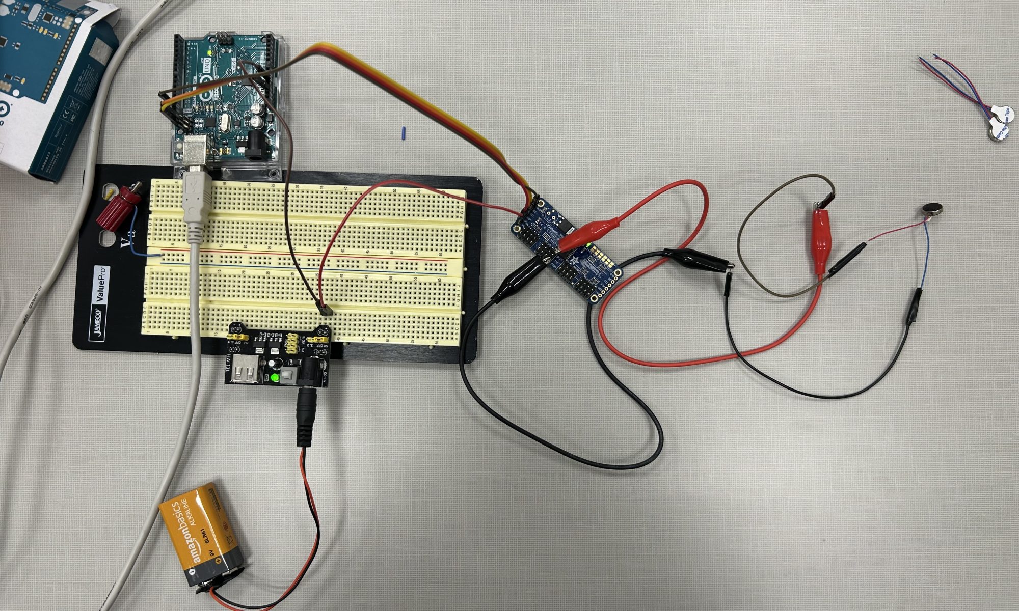
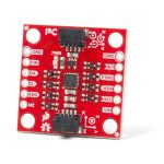
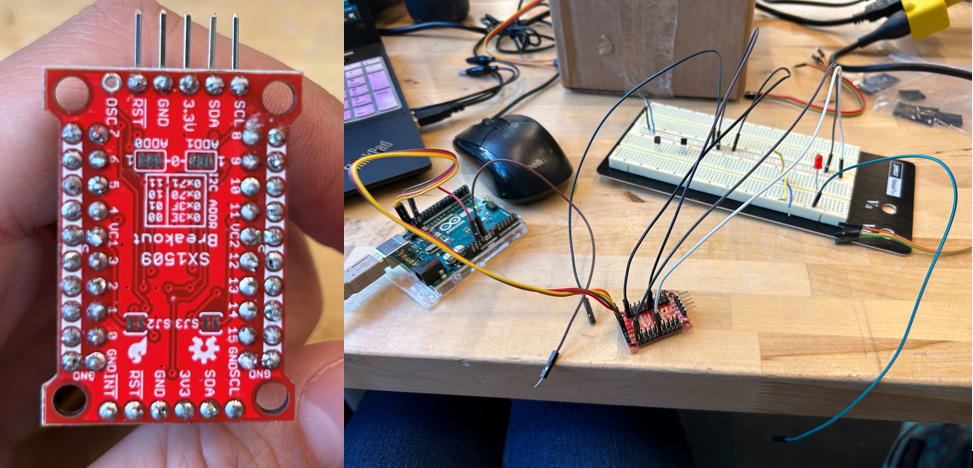
This week I tested out a different option for our I2C motor system driver. The new board I tested was the SparkFun 16 Output I/O Expander Breakout – SX1509. The voltage level and current were lower than the Adafruit servo driver, but this board only needed two wires to run a PWM device. However, through testing, I found that the Adafruit device provided a better option as a motor system driver. 

Figure 1: Sparkfun device soldering and testing

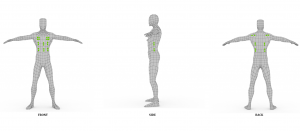
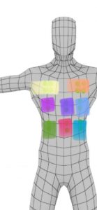
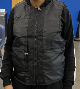
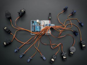
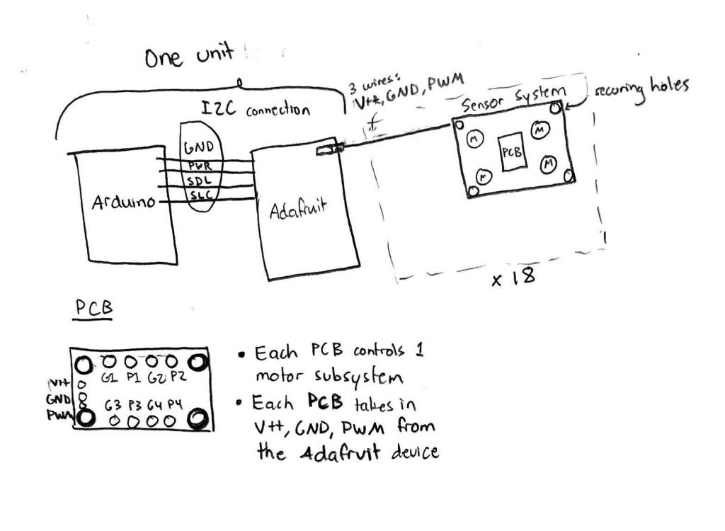
After deciding on a motor system driver, I was finally able to begin a PCB design which would take the PWM signal, V+, and GND from each motor driver output of the Adafruit device and transform that PWM into a voltage level to drive each motor in the motor system. In the original drawing, the plan was to have up to 4 outputs for the possible 4 motors each motor system would run. Amelia then brought up that we might be able to get around this by soldering the ends of the motors together so the PCB would only need one variable V+ output and GND output for the motors. The final design will have the Arduino and Adafruit device close together on the vest. Because these two devices take up the most room (header pins facing outwards), this will limit the bulkiness in the overall vest design. There will then be 16 sets of PWM, V+, GND pins coming out of the Adafruit device going to 16 of the 18 motor subsystems.

Figure 2: Hardware diagram with PCB and motor system

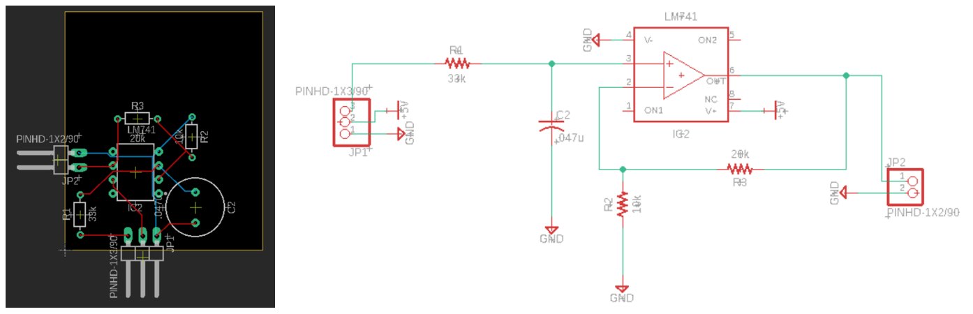
I found a basic PWM to DC voltage conversion online (https://www.egr.msu.edu/classes/ece480/capstone/spring15/group10/Application%20Notes/Kyle.pdf) and began to implement it in Fusion 360 to get a feeling for the tool. I was able to implement the design and discuss with Amelia what the best layout for the PCB would be. 

Figure 3: Testing out opamp circuit on Fusion360

Schedule update

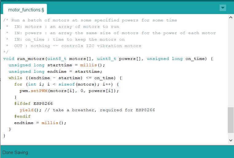
On Sunday, I plan to do some circuit analysis on the current PWM to DC voltage converter. I plan to research which opamp will fit the project the best and go through the problem to figure out the other parts we should need. I will also continue to work on the motor code which I deviated from this week in order to focus on the PCB design. 

Deliverables for next week

I hope to check with Professor Fedder and Omkar on the PCB design before sending out an order. I will then have to go onto DigiKey or a similar website to order the opamps, resistors, capacitors, and other components for the PCB. 

Sophia’s Status Report for 3/4/2023

What did you personally accomplish this week on the project? Give files or photos that demonstrate your progress. Prove to the reader that you put sufficient effort into the project over the course of the week (12+ hours).  

I personally accomplished creating a function that can take in a 2D array of motor pins, 2D array of motor powers, array of timings, and array of pauses. This function can then drive the motors in the given pattern set by the inputs. This is all in the team GitHub under mutlipl_wave.io. It’s print statements are not cleaned up because I’m still probably going to use those with testing further on. I also started to make a Response class which will hold all the motor info so you can just tell the class to “run_response” and have the response you want happen. I started setting up the .cpp and .h files in “BasicDesign” but it’s not functional yet. Lastly, I did some math for what I would need for a PCB to take in 3-wire PWM and make it 2-wire PWM, but I forgot to take a picture of it and don’t have it on hand. Lastly, I also worked on the project report this week.

Is your progress on schedule or behind? If you are behind, what actions will be taken to catch up to the project schedule?  

I am on schedule for what I had planned. However, I had assumed the motors would run properly so that’s a parallel task I’m working on in addition to what I have on the schedule for myself.

I have decided to exchange the Adafruit PWM servo driver for a Sparkfun I/O expander. The expander can do digital, analog, and PWM writes. The one thing I’m unsure of is if it can supply 5V. The device is rated for working up to 5.5V but it has 3.6V operating power. Anyways, it only costs $7, $15 with shipping. I figure I can pick it up when I get back from vacation on Friday, try it out, and then see if I need to come up with the PCB that I talked about last week. And I’ll still be on schedule because I didn’t plan anything for this week.

What deliverables do you hope to complete in the next week?

Absolutely nothing. This is the last thing I am doing before I’m fully on vacation. Once I’m done, I’m checked out. Anything productive will happen when I’m on a beach, soaking up sun and possibly thinking about what I may want to do when I get back.

But the week after, I plan to test the Sparkfun I/O expander. If it worked better than the Adafruit device, I will edit my current code to include it. I also plan to continue to turn the functions to run the motors into a class.


Team’s Status Report for 2/25/2023

What are the most significant risks that could jeopardize the success of the project? How are these risks being managed? What contingency plans are ready?  

The most significant risks that could jeopardize the success of the project are getting the vibrations motors operational. This means we need to come up with a way for the current output from the servo driver to increase. The risks being managed are reassigning tasks to research either a solution to increase current from the PWM pin, or to create a custom PCB to accomplish the task. 

Were any changes made to the existing design of the system (requirements, block diagram, system spec, etc)? Why was this change necessary, what costs does the change incur, and how will these costs be mitigated going forward?  

Additions made to the existing system are adding an extra block between each servo driver output and a vibration motor. This was necessary to ensure the motors will have enough haptic feedback for the gamers to feel. This will increase the cost of the system. A fully custom PCB that connects to the Arduino I2C and outputs PWM on two pins would have been better, however with little experience with creating custom PCB, figuring out custom I2C communication protocols on the PCB may be a bit too much for a first project. 

Provide an updated schedule if changes have occurred. 

If the PCB is designed and sent out before Spring break, it can be tested when we get back.

This is also the place to put some photos of your progress or to brag about  component you got working.

We’ve finalized where on the body the motors should go. We also got our vest in and, despite it coming in a small size when we wanted a larger size, it will work perfectly for the haptic suit. We found that turning it inside out will allow the RGB lights to shine through the material.


Enumerate how you have adjusted your team work assignments to fill in gaps related to either new design challenges or team shortfalls (e.g. a team member missing a deadline).

We have adjusted the team work assignments by compressing some of our larger milestone projects (like programming a motor algorithm) to make space for getting a necessary custom PCB built. 

Sophia’s Status Report for 2/25/2023

What did you personally accomplish this week on the project? Give files or photos that demonstrate your progress. Prove to the reader that you put sufficient effort into the project over the course of the week (12+ hours).  

This week I focused on testing the Arduino to vibration motor system. After playing with the Adafruit GitHub code for the servo driver, I found a way to turn the vibration motors on and off. This was difficult because, as I found while testing, most of the servo driver examples weren’t configured to turn one output on and off, and they never turned on the output long enough for me to see the vibration motor in action. Creating the code and functions to turn the motor on and off led me to realize that I could not connect the motors in the same way I could when connecting them to an Arduino output. 

Figure 1: run motors function

This is because the Arduino supplies enough current (10-15 mA maybe, I forget at the movement and don’t have the parts with me) to make the motors vibrate and the necessary frequency for a solid feedback. However, the servo driver has the GND, V+, and PWM pins. While connecting the vibration motor provides enough current (~8 mA) to sufficiently turn the motor on, the PWM pins provide just current (~0.2 mA, I think) for a 3-wire PWM device to read the voltage level and convert that into how much voltage to draw from the V+ pin. With the vibration motor’s two pins and the PWM’s lack of sufficient current, a new solution is needed to drive the motors. 

Link to video of motor vibrating

Figure 2: the full system working (WordPress doesn’t like videos)

I have come up with a 2-path approach to solve the problem while limiting the impact to the schedule and our plan. The first path is to research how to either 1) drive a 2-wire PWM device from the 3-wire system, 2) “amp” up the current (I’m tired but check out my fun ECE pun…) of the PWM pin, or 3) create a custom PCB to accomplish the first research avenue if that avenue isn’t readily available. The second path is that while I am researching, I can also test and build up my code to run the motors. I don’t need the motors to work perfectly to see if I can properly create a class which can run specific waves of motors at a time for each unique haptic response. For the first path, a fully custom PCB that connects to the Arduino I2C and outputs PWM on two pins would be ideal and maybe I will try to design one if I have time at the end. However, I do not have the amount of experience necessary to design a communication protocol and do not want that to become a time drain when there is another way to accomplish my task.

Is your progress on schedule or behind? If you are behind, what actions will be taken to catch up to the project schedule?  

My progress was on schedule this week. I was successfully able to debug why the vibration motors weren’t turning on. From that, I also created some functions to turn on specific motors for a specified amount of time. For my future schedule, I will be a bit packed before spring break. I believe I will end up making the custom PCB so I need to alter my schedule to make time for that. 

What deliverables do you hope to complete in the next week?

I hope to design a PCB to either increase current from one input to an output, or design a PCB to do similar level checking as 3-pin PWM devices to output a correct current and voltage. 

Sophia’s Status Report for 2/18/2023

Accomplishments this week:

Last week I planned to focus on creating the motor control algorithm due to the uncertainty of getting parts in. On Monday, along with working on our block diagrams and user survey on our physical input system, I worked on my motor control algorithm. This included looking into how the Adafruit I2C device would control the outputs and also how to create classes in Arduino. Amelia was able to test a vibration motor with the Arduino and found it worked with the Arduino’s PWM pin with sufficient vibrational feedback. Testing the motors further would have to wait for the servo driver.

Algorithm: The main issue I found with creating the Response class in Arduino is that I need to come up with a way to make variable sized arrays. The arrays will hold which motors I want to activate for each “wave” of a haptic response. I figure I can either initialize longer arrays that I’ll need then be required to fill with -1’s for the unused indexes, or I can create some sort of variable length char array. Hardcoding various haptic patterns is also an option, but I’d like to make something more variable. However, for initial testing purposes, hardcoding to ensure the variable sized array isn’t causing a bug might be a good starting point. This left me at a point where I would have to know more about the I2C device to successfully use the functions. 

Figure 1: algorithm idea that needs knowledge about I2C controls

Soldering and I2C: Thankfully and unexpectedly, the I2C servo driver and the motors came in on Tuesday. This allowed me to spend Wednesday relearning how to solder so I could solder the header pins onto the servo driver PCB. This, along with doing some tasks with my team,  took most of the class. I ended up finishing the soldering on Friday. I then proceeded to test the vibration motors when they are connected to the I2C device. I did come across some minor issues using the I2C device: the motors don’t seem to run. I used my good old 18-100 debugging circuit skills to try to figure out what was going wrong. The device is set up so there are the GND, SLC, SDA, and VCC pins coming in from the Arduino which provide the signals for the device. Then there is a V+ pin which is connected to a different 5V power supply to supply voltage to the motors. I was able to wire up the I2C device so when I run code to turn on and off an output, you can measure the changing voltage with a multimeter. And I also had some basic servo motors from 18-100 which did move when the code was run. However, the small vibration motors–despite me being able to read a voltage up to 5V from the PWM to GND pins–did not buzz. 

Figure 2: the I2C servo driver PCB board with header pins
Figure 3: simple I2C device setup from Arduino to I2C to vibration motor

Other Stuff: I also worked with Amelia and Bethel on our Design Report presentation.  (Saturday night update: a lot. We worked on the design report presentation a lot). The design report required multiple schematics and wiring diagrams that took a while to design. 

Updates on my schedule:

I am currently on schedule. With the change with the physical input device, my schedule has changed a bit, but my two main tasks of creating the motor algorithm and driving the motors from the servo driver are still on schedule. Although I am going to switch up my schedule because I want to get the motors working properly before moving forward with the algorithm. I believe this will allow me to better understand what functions and parameters the algorithm needs to control.

Deliverables for next week:

Next week is pretty busy for me in most of my classes, but I plan to have some basic working code so specific motors can be signaled to turn on and off given some power and time_on values. This requires me to debug why the power I’m providing to the motors does not cause them to vibrate. Once I have basic function to run one motor, I can easily add them to an class function in Arduino so I can run multiple motors at the same time and in a specific pattern.

List the particular ECE courses (if any) that covered the engineering science and mathematics principles your team used to develop your design

I used 18-100 and 18-220 for the principles on how to set up I2C connections and debug circuits. These classes allowed me to design my system so the ground from the I2C power source was connected to the ground of the Arduino. This is required so they are in the same circuit and weird different-circuit errors don’t occur. I also believe 18-100 had a soldering lesson freshman year so that helped me with soldering the header pins onto the servo drive PCB this week.  I’m also using 15-112 principles for designing my algorithm and creating a class in C++. I think the reason I’m using all my freshman year courses is because it is in those classes I learned the basics of engineering which can be generalized a lot easier than later courses. A lot of my later courses allowed me to improve upon those generalized skills while specializing in other areas. However, most of those specialized skills may not come into play with this project, hence the focus on earlier classes.


Sophia’s Status Report for 2/11/2023

What I did this week:

I spent this week researching what advantage the STM Nucleo boards give us so we don’t end up buying something we won’t benefit from. It turns out that the board will not be as useful as we thought. We are looking to increase the number of PWM outputs while the STM only expands the current outputs to allow for more pin connections. We need to run at least 10 different motor pairs and the Arduino Uno only has 6 built-in PWM pins. After figuring this out, I started to research ways to drive the necessary number of motors. I ended up finding the “Adafruit 16-Channel 12-bit PWM/Servo Driver – I2C interface” which gives us the additional motor controller we need. There are also videos of it being used to successfully use higher power motors than the ones we have. After that research, I focused on ordering parts. 

Adafruit 16-Channel 12-bit PWM/Servo Driver

This week, I also researched accelerometers, Bluetooth transceivers, and hardware controllers we would need for the physical input we want to add to our game. This was after our interview with Mimi and the feedback that a physical input option would be great (talked about more in the team status report). I found there is a relatively inexpensive IMU on Sparkfun that can connect to Arduino, and found a Bluetooth transceiver which is used in multiple project demos across the internet, and found the Arduino Micro or Nano to be small enough to fit on the physical input “stick”.

Sparkfun IMU I2C device
Wireless Bluetooth RF Transceiver

Update on if the project is on schedule:

On the schedule, I believe we are going to be a couple days behind. This is due to the fact that I had created my schedule thinking I would have time to research parts on Monday and hopefully order by Wednesday. With class time dedicated to watching project proposals this week, parts ordering got pushed back to Thursday. With the way the parts ordering works, I am unsure if I have to wait until next Tuesday before the order goes through. This could lead to further delays as I had planned to get our parts in by the middle of next week. 

One consideration that will help me stay on schedule is that in the original schedule, I had also planned to make a PCB to control the motors. With the Adafruit servo driver, I do have some wiggle room. To stay on schedule, I plan to start creating the code to control the motors and I2C device so I will be ready to test by the time they come in.

Deliverables for next week:

By the end of this week (I’m writing this Friday morning), I hope to do one last review on the parts for the physical input and order them. Next week, I plan to get started with writing an algorithm to activate multiple motors at the same time. This will include drawing out an outline for how I want to take in data and design the overall architecture for accomplishing my part of the project. 

I will also have to work with Bethel and Amelia on our design presentation deliverables.


Team Status Report for 2/11/2023

The most significant risk that could jeopardize the success of the project is not receiving our parts in time, which would push our planned schedule back. We also have to consider researching the best motors for our chosen haptic feedback points before ordering (this is going directly out of our budget so we don’t want to spend excessively on motors we won’t end up using). However, we have to consider that ordering one type of motor at a time would delay our project if it turns out that the chosen motor type does not meet our requirements. To mitigate this risk, we have our own personal motors/Arduinos that we will be using for testing while we wait for our parts.

On Sunday, we had an additional meeting with Mimi Sung, the president of CMU Esports (student-run gaming organization). She brought up a valid point that even if we provide excellent haptic feedback, the fact that the gamer is still confined to a keyboard may diminish the full feedback experience. This inspired us to consider adding a physical input device so that the user can control their in-game actions without the use of a keyboard. 

This physical input device we first thought to build is a wireless joystick modeled after the nunchuck controller joystick (as shown in Figure 1 and 2). The joystick in the player’s left hand will control the movement of the player, while the joystick in the player’s right hand will include buttons (as shown in Figure 3) that can control the player’s actions (i.e. forceful jump, attacking an enemy, diminishing health and getting hit).

Figure 1
Figure 2
Figure 3


Another avenue we could take to achieve a keyboard-free experience could be taking a regular wireless Xbox controller and configuring it to the monitor the game is being played in (as shown in Figure 4). We would have to find a way to configure the X-Y-A-B keys on the controller to W-A-S-D keys on the keyboard, and get that information to the game itself. It’s a possible avenue, but definitely needs more research before we decide to go with it or build our own nunchuck controller.

Figure 4

In consideration of our meeting with Mimi, we changed our project proposal and gantt chart to reflect creating the keyboard-free experience. We allotted time to research, develop, and test this system. 

Our project includes considerations for the welfare, safety and economic capability of our intended user. A driving force of our project is to make our haptic suit cheaper than the industry standard which runs around $500-$3000, our solution will run for less than $200. We also aim to design our system around all sizes, in order to promote body inclusivity and comfortability from wearing our vest.