I finished the inside of the vest.
Figure 1: The inside of the back of the vest. All wiring and pockets completed.
Carnegie Mellon University: ECE Capstone Spring 2023 | Amelia L. Bethel Y. Sophia L.
I finished the inside of the vest.
Figure 1: The inside of the back of the vest. All wiring and pockets completed.
What are the most significant risks that could jeopardize the success of the project? How are these risks being managed? What contingency plans are ready?
We need to make the integration more reliable.
One of the risks we could encounter is a problem we didn’t foresee. We hope to mitigate this by doing more user testing so other people can help uncover unknown problems. We completed about 1 hour of user testing today. As a contingency plan for if any hardware breaks, we have about ½ of our hardware resources as backups in case something breaks or something goes wrong.
Another risk we are preparing a contingency plan for are wiring issues. We tried to mitigate this risk by using ribbon cable to improve clarity of cabling, making debugging far easier.
Were any changes made to the existing design of the system (requirements, block diagram, system spec, etc)? Why was this change necessary, what costs does the change incur, and how will these costs be mitigated going forward?
We finally changed the block diagram to include the PCBs. Some minor motor system numbers were changed to fit with the actual wiring of the vest.
We pivoted from using the Puppeteer library to track the remaining three in-game actions of low health, getting hit by a small enemy and getting hit by a large enemy. The problem with this library lies in the fact that it didn’t allow us to customize the game as per our user and design requirements. An instance of this was our lack of ability to incorporate the motor intensity bar into the user interface as was expressed through our Ethics feedback session.
Provide an updated schedule if changes have occurred.
This is also the place to put some photos of your progress or to brag about a component you got working.
What did you personally accomplish this week on the project? Give files or photos that demonstrate your progress. Prove to the reader that you put sufficient effort into the project over the course of the week (12+ hours).
I’ve done a lot. I’ve completed most of the physical design of the suit in the past two weeks. This included a lot of sewing of the motor system velcro pieces into the front part of the vest. Frankly, this took way too long as the sewing machine didn’t always work. But it was something that had to be done and was a good filler while I waited for the rest of the PCBs to arrive. Once the PCBs arrived, I used solder paste and assembled 16 more sets to be used in the vest and as backups with some help from Amelia and Bethel. Then I went ahead and wired the 8 motor systems for the front of the vest and wired the lights into the vest. Then I fixed some motor functions to update them to some wiring changes I made.
Throughout this process, I continually tested each step to ensure that an issue on one motor system didn’t propagate to the whole vest. When learning how to use solder paste, I finished one PCB and tested it to ensure I did it correctly. After soldering all the PCBs I tested each and removed the ones that didn’t work for debugging later. Finally, I tested the motor functions before putting any motors into the vest. These steps of validation helped me remove any uncertainties and harder debugging later in the process.
Figure 1: All the PCBs soldered and sewed into their rubber mounting plates
Figure 2: Example of the inside of the vest
Is your progress on schedule or behind? If you are behind, what actions will be taken to catch up to the project schedule?
I think we can get our project done. I’m a bit behind schedule as I need to add the velcro for the motor system holders to the back of the vest. I didn’t do it before now because 1) I wanted to get at least the front of the vest working so we could test integration and 2) I have come to hate the time sink that swing is for this project.
What deliverables do you hope to complete in the next week?
I will help Amelia debug why the lights don’t work in the vest. I will sew all the motor systems into the back of the vest. I will update the motor algorithms to handle the new motors in the back.
What are the most significant risks that could jeopardize the success of the project? How are these risks being managed? What contingency plans are ready?
Since the PCB arrived this week and works as intended, the next significant risk would be not getting the proper data sent between the Node JS server and the WIFI Rev. This step is integral towards having a completely wireless experience when using our solution. As of now, the Node JS code is able to send data to the WIFI Rev, it’s just not the game data we want. We do want to move forward in order to get to the testing and validation stage of our project, so if we can’t get it to work by the end of the week, we will revert back to having a wired arduino to the laptop. The arduino is able to respond to Node JS data when it is connected to a specific port, as Bethel demonstrated in earlier status reports so we should have no problem if we switch to this.
Were any changes made to the existing design of the system (requirements, block diagram, system spec, etc)? Why was this change necessary, what costs does the change incur, and how will these costs be mitigated going forward?
Since we had an interim demo this week, we ordered ribbon cables and the remaining PCB parts. The PCBs were a component we added on later within our design process. Our current design of our motor systems benefit from having an efficient distribution of power to our motors, which makes for both a bettered immersive experience and more distinguishable motor propagations for the user
Additionally, we decided to laser cut our “pocket” squares in order to achieve a more uniform look and stay consistent with sizing. This saved us a considerable amount of time as well, since we no longer have to sit and manually cut 10+ squares. We used fabric that was free and available to us through IDEATE.
Provide an updated schedule if changes have occurred.
We don’t have an updated schedule, but plan to start validation testing by 4/14. Given that the rest of the PCBs will not arrive by then, validation will take us up till the final demo.
What did you personally accomplish this week on the project? Give files or photos that demonstrate your progress. Prove to the reader that you put sufficient effort into the project over the course of the week (12+ hours).
I was able to start assembling the PCBs and start testing them. The PCBs and parts arrived Wednesday, which wasn’t in time to use them for the interim demo, but I was able to start testing them afterwards. On Wednesday, I put together one motor system and verified that it worked as intended. With the PCB assembled, Amelia was then able to size and laser cut the final motor system holders out of the final rubber material. After putting together the rest of the 5 PCBs I had on hand, I mounted one PCB to the motor system. Along with the laser cut fabric pockets, we now have our final vest assembly components.
To move forward with the final vest assembly, I am also in charge of reversing the zipper on the best as we turned the vest inside out for our project. I was able to test removing and sewing the vest on the demo vest.
Figure 1: Soldered PCBs
Figure 2: The final motor system assembly
Is your progress on schedule or behind? If you are behind, what actions will be taken to catch up to the project schedule?
I would like to be further ahead on testing in order to receive more user feedback, but I am currently on schedule to finish my project.
What deliverables do you hope to complete in the next week?
I hope that the rest of the PCBs will come in late next week. For early in the week, I will work on vest assembly and hope to reverse the zipper on the final vest, install the fabric pockets for the motor systems, and begin the final wiring if the rainbow ribbon cable comes in time.
Now that you are entering into the verification and validation phase of your project, provide a comprehensive update on what tests you have you run or are planning to run. In particular, how will you analyze the anticipated measured results to verify your contribution to the project meets the engineering design requirements or the use case requirements?
For validation, I plan to check the technical side of the motors as well as collect some user data for the sensations of the motors. For the technical checks, I need to determine how quickly different responses will take to run and how to make them differentiable. This ties into the use case requirements of allowing for 10+ responses per minute and providing unique feedback patterns. Currently, I need to do a bit more work before I collect user input. I will position the motor system pockets and then ask for user feedback on the motor sensations. With only five PCBs currently, I will most likely have to rotate the motors test test the sensations for different parts of the torso.
What are the most significant risks that could jeopardize the success of the project? How are these risks being managed? What contingency plans are ready?
Keeping an organized wiring system is one of the most significant risks going forward. For our demo, we have 22 gauge wires from the Arduino to each motor. This takes up a lot of space and for the 6 motor systems we have, the cable management is getting pretty messy. We currently have 5 colored wires for the 6 systems, but when we reach 18 motor systems we’re going to need a better system. For the demo, we’ve made a wiring diagram to reference that can be found here. Moving forward, to manage these risks for the final, we plan on using ribbon cables and crimp pin connections. With ribbon cables, we can have one bus of cables which are flat and organized. When the cable reaches a motor system, it will branch out to connect to the system.
Were any changes made to the existing design of the system (requirements, block diagram, system spec, etc)? Why was this change necessary, what costs does the change incur, and how will these costs be mitigated going forward?
The orientation of the motors within their casing needs to be turned 90 degrees to the left (clockwise) in order to minimize the risk of breakage.
For the interim demo, we are changing how we implement the motor holders, power system for the lights, and motor system driving device. For the motor holdings, we are using cardboard instead of the rubber we plan to use for the final. This is to save money in our prototype system. We are using a 6V battery supply made up of 4 AA batteries instead of the 9V battery with a buck converter we plan to use in the final. This is because we are currently waiting for the buck converter to come in. Lastly, we are using the Arduino to power the motor systems instead of the servo driver device. This is for several reasons. The servo driver device does not provide enough power to drive the motor systems until we receive our PCB boards. We want to deliver a product that can provide the sensations we want for the final project so we are instead wiring the motor systems directly to the Arduino board. The board is limited to 6 PWM outputs so this solution will not work for the final.
Provide an updated schedule if changes have occurred.
Individual tasks of each member will be updated to be taking place simultaneously with our integration of the software and hardware components.
With regards to the software side of things, we are still looking to track the low health, small hit and large hit game events. Moreover, we look to incorporate our PCB to our original design the moment it arrives.
This is also the place to put some photos of your progress or to brag about a component you got working.
Cascading lights
Progress with wiring up our motor systems
I finished the PCB and submitted the order for printing as well as the order for the necessary parts. I went through many iterations of the PCB with lots of help from Professor Fedder and Omkar. I was able to learn how to choose different parts for the PCB and check on Digikey for those parts in the specified packaging and requirements. I worked with Amelia to design the PCB to fit into the laser cut patterns she is making to hold each motor system. The length of the board takes up the length of the two motors while allowing a minimal width of the PCB. Finally, I submitted the PCB fabrication design on JLCPCB and the parts list on Digikey. I also met with Amelia and Bethel Friday and Saturday to discuss and begin implementing our individual contributions.
I am on schedule. The PCB hadn’t fully incorporated itself into the schedule so I did free some time up by delaying when I will upgrade my motor control algorithm. The current mindset for last week and next week has been on creating everything semi-functional for the interim demo. The current motor control is a bit clunky code-wise but the outcome is sufficient to show a working demo. I was able to work on control more today and plan to continue to refine it in between the critical tasks would keep the project from moving
I hope the PCB board and parts will come in early next week so that I have time to solder and test them. This way we are able to produce strong vibration feedback for the interim demo. If the PCB comes in later in the week I will have time to work on my code and integration with Bethel and Amelia to prepare for the demo.
Figure 1: The PCB wiring diagram
Figure 2: The PCB part layout
Figure 3: The PCB 3D rendering
Figure 4: PCB fabrication design
What are the most significant risks that could jeopardize the success of the project? How are these risks being managed? What contingency plans are ready?
We were very careful and sought a lot of feedback from our TA and professor when designing our PCB for the motor systems. However, there could still be an unforeseen problem when we start to test them next week. Without the PCB, our vibrational feedback will not be as effective and may jeopardize the sensations we want our users to feel.
We also noticed that the RGB lights draw a significant amount of current, so much so that the 6V battery supply to the microcontroller was not enough to keep all the lights running at a high brightness setting. If we add a second power supply, the lights are able to run at a high brightness and there is some heat emission. The heat emission is not noticeable or uncomfortable when you put on the vest, only if you place your hand directly over the lights. We don’t anticipate the heat of the lights being a risk factor, but we did want to acknowledge it.
Were any changes made to the existing design of the system (requirements, block diagram, system spec, etc)? Why was this change necessary, what costs does the change incur, and how will these costs be mitigated going forward?
This week, we had our ethics discussion. The other groups brought up several points we did not originally consider in our design. One of the biggest concerns brought forward was the idea that someone could remotely control the vest using the wireless controller. When we decided to move to a fully remote system, we had not considered how incorporating a remote controller might be dangerous to the person inside the vest. To avoid this, we plan on implementing an emergency stop switch into the vest which can turn everything off immediately. This will allow people who feel uncomfortable to stop the vest. This emergency stop will be a physical system between the power and the devices that are running, preventing any delays sending a signal to the Arduino may cause.
Other concerns included how hot the vest would get and how accessible our product would be for people who have limited arm mobility. For the heat, we were able to test it out, as stated in our risk factors. We interpreted the latter as a concern of putting on the physical vest. To make putting on the vest a smoother experience, we decided to put optional Velcro strips that run horizontally across the middle of the vest (under the zipper) so that a user is able to secure these strips instead of the zipper, which may be hard to use.
A design change we made this week was the inclusion of Velcro strips to the inside lining of the vest in order to vertically secure the light and motors systems. The user will not see these strips, but it does allow us as the designers to easily access the motors/lights, provides minimal movement, and a seamless outside look that avoids any additional sewing.
Provide an updated schedule if changes have occurred.
We are on schedule. Next week, we will focus on integration and cleaning up our individual contributions.
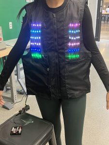
What we got working. Video of putting on the vest can be found here.


The PCB needs to be designed and simulated before sending the design out for printing. If we don’t get the design sent out soon, this might delay our current plan to have a basic full-system operation working before the interim demo. We are going to manage the risk of not getting it done in time by finishing the design by Monday of next week. This will allow us about one week of printing time and one week to test the full hardware with the PCB. Our interim demo is in 2 weeks, so we hope to have a full system demo for at least one in-game action working by then. Our contingency plan is to have the interim demo with only one motor in each subsystem directly connected to the motor driver. This will allow the users some idea of how the feedback system will work even if it won’t provide the amount of feedback we plan to have for the final.
Upon consulting with Omkar and Professor Gary Fedder, we have decided to completely abandon the game code translation process. Instead we will be going back to the original strategy of using JavaScript event listeners to track different game actions. This changes our software design in that we will be using socket.io to relay information to the Node JS server and the server will then use the serial port package to send this information to our Arduino. This change was necessary because limited progress was made in transferring the AI component of the game code from Javascript, HTML and CSS to Node JS.
Additionally, we previously had differing ideas on how the PCB would be mounted and connect to the motors, but upon our meeting with Professor Gary and Omkar this week, we decided that the motors should be mounted separately, and the PCB should be attached to the motor mounting plate instead of it being one entire system. This will make our design more modular to changes since it’s easier to laser cut a new mounting plate than it is to design a new PCB if we want to make slight changes to the motor positions.
N/A. Somehow, we’re not off schedule yet.
