Bethel’s Status Report for 3/25/2023

What did you personally accomplish this week on the project? Give files or photos that demonstrate your progress. Prove to the reader that you put sufficient effort into the project over the course of the week (12+ hours).  

My team and I attended Wednesday’s Ethics Lecture and meticulously made notes on the ethical considerations brought up by our peers within our Pods discussion. We do plan to incorporate the feedback we received to our existing design as expressed within our Team Status Report. 

This week has been particularly productive, in that I was able to complete both of my planned deliverables while also using the STEAM platform to configure the wireless controller to game play settings with the generous help of both of my teammates as shown in the video clip titled “Controller_to_Game_Integration.MOV” within our Google Drive. One of my two deliverables for this week involved me having to integrate the Node JS server with the forceful jump event’s game data. This helps confirm whether the Node JS server can relay our game data successfully to our simple motor circuit. This was successfully achieved as result of the effective testing of the Node JS server I conducted last week which allowed me to easily pinpoint the bugs within my integrated code and fix them.   

My second deliverable for this week consisted of testing the Node JS server on the Arduino WIFI Rev while it is still connected to my PC, before proceeding on to establishing a wireless connection. This was efficaciously achieved on Friday, 24th March with the assistance of my teammate Amelia. 

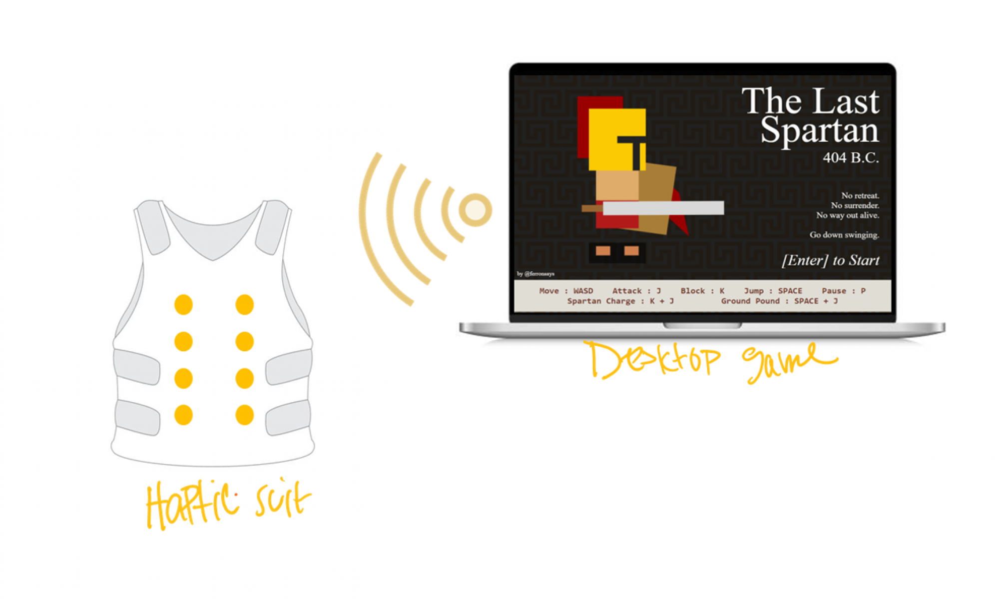
I also changed the game action keys on the frontend of the game to match that of our controller configurations as an added customization to The Last Spartan. We utilized the mappings expressed within our design report whereby the W-A-S-D keys correspond to the left-most joystick; the “k” key corresponds to the left trigger/ left bumper; “j” key right trigger/ right bumper; “p” key corresponds to the “Options” buttons; “SPACE” key corresponds to button “A” and the “ENTER” key corresponds to button “B”.

I eventually played the game wirelessly to test all the integrated components together while also measuring latency of our system by taking a video of the motor activations that occur in response to forceful jump events. According to the video I believe that my software system has minimal latency as shown in the video clip titled “Game_Data_to_Server_Integration.MOV” within our Google Drive. 


Is your progress on schedule or behind? If you are behind, what actions will be taken to catch up to the project schedule?  

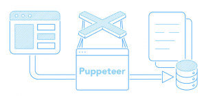
My progress is somewhat back on track since I have managed to successfully integrate the Node JS server and the JavaScript listeners that track the forceful jump game action. I still have to integrate my software components with the hardware components that my teammates have built in order to have a working prototype by the time we have our interim demo. I will still be focusing on how to use Puppeteer to acquire data from all the remaining game actions for this upcoming week. 


What deliverables do you hope to complete in the next week?

This week I plan to incorporate a web scraper library known as Puppeteer in my existing software to aid in tracking the game actions of the remaining three events, namely small hit, large hit and low health. Puppeteer will help me analyze different enemy actions in order to accurately transfer data relevant to the game action taking place. For instance, we would not want a low health event to be flagged every time the life bar decreases, instead we would like this event to be activated when the bar decreases to 25% of its original length. 

Moreover, I plan to test my software on the Arduino WIFI Rev after establishing a wireless connection.


Amelia’s Status Report 3/25

Updates for the week

This week, I worked on getting the RGB lights (Adafruit DotStrips) to turn on in a specific pattern, placing them inside the vest, laser cutting the motor mounting plate, integrating the wifi REV with Bethel, and integrating the light system wiring to the vest with my entire team.

To turn on the lights, I used the Adafruit_DotStar library on the Arduino IDE and connected the datapin to 4, clockpin to 5, power to Vin, and ground to GND on the Arduino. Next, I set the all the LEDs’ red channel to high.  From there I did a simple flashing motion to simulate a “low health” event.  The low health light show only turns on when a user is below 25% health. As the user’s health decreases from this threshold, the faster it will flash red until the user dies, upon which the LEDs will stay red. For the forceful light response, we will have a cascading wave moving up then down to showcase this event occurred. I isolated the light indexes into rows/cols and which can be shown in the figure below (60 LEDs, 30 on the left and 30 on the right).

Figure 1: Light system on, separated by rows

Next, I worked on de-threading the bottom of the vest so that I could put the LEDs inside the lining of the vest and see how they shine. A video of this can be seen here. Since the lights need to be accessible to me (so that I could move them in/out of the vest as need), this meant that I also need a way to open and close the part of the vest I just de-threaded. For this, I placed Velcro strips on the inside lining that I could just pull/push together in order to open/close. I found this made the design still look seamless, and I could apply this solution to securing the light/motor systems to the vest, rendering my “pocket” solution I brainstormed in earlier weeks obsolete.

I also began experimenting with a different material for the motor mounting plate. I landed on rubber since it is cheap and flexible. I worked on laser cutting the .dxf file I made last week on this material, and the output of that can be seen in Figure X and X+1. I added additional space to the right of the motor holes so that we can place the PCB once it’s ready.

Figure 2: Motor mounting plate

Eventually, the motors will have a spring attached to the back that will make sure there is contact with the motors and the torso of the user, regardless of their size. A rough idea of it is shown in the figure below.

Figure 3: Coin motor with a spring attached

Lastly, I worked with Bethel this week to ensure her part of the project was working with the Arduino Wifi Rev. We worked together so that she didn’t have to repeat any code that’s already written and so that we are able to see if the Arduino is able to receive a simple JSON message (“1” or “0”) she is sending. We were able to see the message, but need to work on sending more information-rich messages that explain an event like forceful jump, low health, getting hit by a small enemy, etc. etc. that are relevant for motor and light responses. After talking it through, we decided the simplest message that the JSON could send are 2, 1-hot vectors since her event precedence algorithm will mean that only one event is registered at a time .This moves away, but has the same essence of the message I worked on parsing last week.

Progress On Schedule

I’m still on schedule, especially now that I’ve gotten the light system up and working. I have also been integrating more with my team, which is a good sign as interim demo is coming up in the next two weeks.

Deliverables for next week

Next week, I plan on finalizing the forceful jump and low health light show timings with Sophia’s motor responses for the same events. The idea is that they last about the same amount of time with their respective motor event.

I will also continue working with Bethel to ensure the Wifi Rev is responding to her message wirelessly and with minimal latency that is within our design requirements.

I will also laser cut a set of motor mounts using cardboard to have ready for the interim demo. If the PCB arrives before Thursday, I will laser cut the mounts using the rubber material.

Sophia’s Status Report for 3/25/2023

Accomplishments this week

I finished the PCB and submitted the order for printing as well as the order for the necessary parts. I went through many iterations of the PCB with lots of help from Professor Fedder and Omkar. I was able to learn how to choose different parts for the PCB and check on Digikey for those parts in the specified packaging and requirements. I worked with Amelia to design the PCB to fit into the laser cut patterns she is making to hold each motor system. The length of the board takes up the length of the two motors while allowing a minimal width of the PCB.  Finally, I submitted the PCB fabrication design on JLCPCB and the parts list on Digikey. I also met with Amelia and Bethel Friday and Saturday to discuss and begin implementing our individual contributions. 

Schedule Update

I am on schedule. The PCB hadn’t fully incorporated itself into the schedule so I did free some time up by delaying when I will upgrade my motor control algorithm. The current mindset for last week and next week has been on creating everything semi-functional for the interim demo. The current motor control is a bit clunky code-wise but the outcome is sufficient to show a working demo. I was able to work on control more today and plan to continue to refine it in between the critical tasks would keep the project from moving

Deliverables for next week

I hope the PCB board and parts will come in early next week so that I have time to solder and test them. This way we are able to produce strong vibration feedback for the interim demo. If the PCB comes in later in the week I will have time to work on my code and integration with Bethel and Amelia to prepare for the demo. 


Figure 1: The PCB wiring diagram

Figure 2: The PCB part layout

Figure 3: The PCB 3D rendering

Figure 4: PCB fabrication design

Team Status Report for 3/25/2023

What are the most significant risks that could jeopardize the success of the project? How are these risks being managed? What contingency plans are ready?  

We were very careful and sought a lot of feedback from our TA and professor when designing our PCB for the motor systems. However, there could still be an unforeseen problem when we start to test them next week. Without the PCB, our vibrational feedback will not be as effective and may jeopardize the sensations we want our users to feel. 

We also noticed that the RGB lights draw a significant amount of current, so much so that the 6V battery supply to the microcontroller was not enough to keep all the lights running at a high brightness setting. If we add a second power supply, the lights are able to run at a high brightness and there is some heat emission. The heat emission is not noticeable or uncomfortable when you put on the vest, only if you place your hand directly over the lights. We don’t anticipate the heat of the lights being a risk factor, but we did want to acknowledge it. 

Were any changes made to the existing design of the system (requirements, block diagram, system spec, etc)? Why was this change necessary, what costs does the change incur, and how will these costs be mitigated going forward?  

This week, we had our ethics discussion. The other groups brought up several points we did not originally consider in our design. One of the biggest concerns brought forward was the idea that someone could remotely control the vest using the wireless controller. When we decided to move to a fully remote system, we had not considered how incorporating a remote controller might be dangerous to the person inside the vest. To avoid this, we plan on implementing an emergency stop switch into the vest which can turn everything off immediately. This will allow people who feel uncomfortable to stop the vest. This emergency stop will be a physical system between the power and the devices that are running, preventing any delays sending a signal to the Arduino may cause. 

Other concerns included how hot the vest would get and how accessible our product would be for people who have limited arm mobility. For the heat, we were able to test it out, as stated in our risk factors. We interpreted the latter as a concern of putting on the physical vest. To make putting on the vest a smoother experience, we decided to put optional Velcro strips that run horizontally across the middle of the vest (under the zipper) so that a user is able to secure these strips instead of the zipper, which may be hard to use.  

A design change we made this week was the inclusion of Velcro strips to the inside lining of the vest in order to vertically secure the light and motors systems. The user will not see these strips, but it does allow us as the designers to easily access the motors/lights, provides minimal movement, and a seamless outside look that avoids any additional sewing. 

Provide an updated schedule if changes have occurred. 

We are on schedule. Next week, we will focus on integration and cleaning up our individual contributions. 

What we got working. Video of putting on the vest can be found here

Figure 1: Vest light integration
Figure 2: Vest on mannequin
Figure 3: Clean wiring through suit

Bethel’s Status Report for 3/18/2023

What did you personally accomplish this week on the project? Give files or photos that demonstrate your progress. Prove to the reader that you put sufficient effort into the project over the course of the week (12+ hours).  

My team and I brainstormed and compiled a variety of ethical considerations concerning our project in preparation for the ethics lecture and group discussion. 

This week I was able to track the forceful jump game event successfully using JavaScript event listeners. I have decided to incorporate a web scraper library known as Puppeteer to aid in tracking the game actions of the remaining three events, namely small hit, large hit and low health. Puppeteer will help me analyze different enemy actions in order to accurately transfer data relevant to the game action taking place. For instance, we would not want a low health event to be flagged every time the life bar decreases, instead we would like this event to be activated when the bar decreases to 25% of its original length. 

Figure 1. Shows how Puppeteer interacts with the live data inputs coming from the browser which it passes on to our Node JS server.


After building the Node JS server last week, I tested my code using a two button webpage, whereby the “Turn Motor On” button represents the activation of a game action and the “Turn Motor Off” button deactivates the motor as shown in Figures 2 & 3. This helps test the proper functionality of the Node JS server while it is in the early development stage. Furthermore, I have designed a single motor circuit using an Arduino Uno as shown in Figure 1. to simplistically mimic the behavior of our system of motors.

Figure 2. Shows the simple two button webpage I used to test the functionality of my Node JS server.

Figure 3. Shows the simple Arduino code I used to test the functionality of my Node JS server.


Is your progress on schedule or behind? If you are behind, what actions will be taken to catch up to the project schedule?  

My progress is somewhat back on track since I have managed to build the Node JS server based on dummy data and successfully track one game action. I still have to integrate the two components together and test them in unison before I proceed. I will also be focusing on how to use Puppeteer to acquire data from all the remaining game actions as well. 


What deliverables do you hope to complete in the next week?

This week I plan to integrate the two components to see whether the Node JS server can relay our game data successfully to our simple motor circuit. Moreover, I plan to test my software on the Arduino WIFI Rev while it is still connected to a PC, before moving on to establishing a wireless connection.


Amelia’s Status Report for 3/18

Updates for the week

This week, I focused on parsing the POST request data from POSTMAN. I got this to work successfully, but after consulting with my teammates Bethel and Sophia about what the incoming data is going to look like, I realized that parsing data from POSTMAN is not the same as parsing data from JSON, but we agreed that any incoming data will have the string format “? MA, LA”

Where MA is a string that holds any of the 5 string values: ”  “, “FJ”, “HS”, “HL”, “LH” corresponding to a motor action (i.e. FJ->Forceful Jump, HS->Hit Small, HL->Hit Large, LH->Low Health). LA holds similar 5 values: ”  “, “W”, ” HS”, “HL”, “W” which corresponds to a light show action (i.e. W-> character in water).

I will parse this string format and hold the corresponding values in a struct so that the motor and light algorithms are able to case on these value instantly and send the correct response to the motors/lights.

These will start with a ‘?’ to let the IDE know we’re receiving the proper data.

Next, I worked on prototyping the actuator mounting board. I started by creating a CAD model with squares and added 2 mounting holes 10mm in diameter to these squares. I laser cut them on (1/32)” cardboard then realized the motor surfaces weren’t flush with the cardboard because they didn’t have a notch for the wires in sticking out of the motors. I then added a notch on CAD and did several iterations of prototyping on cardboard. I laser cut on slightly thicker cardboard but the motor just fell out because the gap couldn’t support the motor, then went back to prototyping on (1/32)” thick cardboard. The image below shows the iterating process. I finally landed on a design which has holes 9.7mm in diameter (slightly smaller to ensure the motor doesn’t fall out) and a gap of 5mm between the two motors. I also tested these at half/full power and it wasn’t unpleasant at 5 mm apart, and did not fall out of the mounting hole.

I also worked on setting up the RGB lights. I turned on 1 LED but need to spend more time on it in order to have the Low Health light show functional as I stated in last week’s status report.

Progress On Schedule

Since I am no longer designing the PCB board, I only have to focus on getting the lights working, the motor mounting plate finalized, and Arduino working wirelessly. I have the Arduino working wirelessly already, it’s just a matter of parsing data from JSON, not from POSTMAN. I’m behind on getting the light algorithm working, so I will spend tomorrow (3/19) working on it.

Deliverables for next week

For the final motor placements, I’m intending on using a different, more durable material. I’m hoping to finalize choosing which material this is going to be, I’m in-between acrylic or a silicone sheet because of its lightweight and heat resistance. I plan on talking with the professor more about the pros/cons of each material.

Once Sophia has the finished dimension for the PCB, I plan on editing the CAD model to make space for the PCB on the actuator mounting board and laser cutting 8 of these to have them ready for the interim demo. The idea is that these 8 will go on the front of the vest, and I will make a plan to mount + wire them on the vest so that they do not move.

I will also get the low health light show algorithm working by the end of the week, so that we are in good standing to have at least one action completely done before the interim demo.


Team Status Report for 3/18/2023

Most Significant Risks

The PCB needs to be designed and simulated before sending the design out for printing. If we don’t get the design sent out soon, this might delay our current plan to have a basic full-system operation working before the interim demo. We are going to manage the risk of not getting it done in time by finishing the design by Monday of next week. This will allow us about one week of printing time and one week to test the full hardware with the PCB. Our interim demo is in 2 weeks, so we hope to have a full system demo for at least one in-game action working by then. Our contingency plan is to have the interim demo with only one motor in each subsystem directly connected to the motor driver. This will allow the users some idea of how the feedback system will work even if it won’t provide the amount of feedback we plan to have for the final. 

Changes to Existing Design

Upon consulting with Omkar and Professor Gary Fedder, we have decided to completely abandon the game code translation process. Instead we will be going back to the original strategy of using JavaScript event listeners to track different game actions. This changes our software design in that we will be using socket.io to relay information to the Node JS server and the server will then use the serial port package to send this information to our Arduino. This change was necessary because limited progress was made in transferring the AI component of the game code from Javascript, HTML and CSS to Node JS.

Additionally, we previously had differing ideas on how the PCB would be mounted and connect to the motors, but upon our meeting with Professor Gary and Omkar this week, we decided that the motors should be mounted separately, and the PCB should be attached to the motor mounting plate instead of it being one entire system. This will make our design more modular to changes since it’s easier to laser cut a new mounting plate than it is to design a new PCB if we want to make slight changes to the motor positions. 

Updated Schedule

N/A. Somehow, we’re not off schedule yet. 

Sophia’s Status Report for 3/18/2023

Accomplishments this week

This week I tested out a different option for our I2C motor system driver. The new board I tested was the SparkFun 16 Output I/O Expander Breakout – SX1509. The voltage level and current were lower than the Adafruit servo driver, but this board only needed two wires to run a PWM device. However, through testing, I found that the Adafruit device provided a better option as a motor system driver. 

Figure 1: Sparkfun device soldering and testing

After deciding on a motor system driver, I was finally able to begin a PCB design which would take the PWM signal, V+, and GND from each motor driver output of the Adafruit device and transform that PWM into a voltage level to drive each motor in the motor system. In the original drawing, the plan was to have up to 4 outputs for the possible 4 motors each motor system would run. Amelia then brought up that we might be able to get around this by soldering the ends of the motors together so the PCB would only need one variable V+ output and GND output for the motors. The final design will have the Arduino and Adafruit device close together on the vest. Because these two devices take up the most room (header pins facing outwards), this will limit the bulkiness in the overall vest design. There will then be 16 sets of PWM, V+, GND pins coming out of the Adafruit device going to 16 of the 18 motor subsystems.

Figure 2: Hardware diagram with PCB and motor system

I found a basic PWM to DC voltage conversion online (https://www.egr.msu.edu/classes/ece480/capstone/spring15/group10/Application%20Notes/Kyle.pdf) and began to implement it in Fusion 360 to get a feeling for the tool. I was able to implement the design and discuss with Amelia what the best layout for the PCB would be. 

Figure 3: Testing out opamp circuit on Fusion360

Schedule update

On Sunday, I plan to do some circuit analysis on the current PWM to DC voltage converter. I plan to research which opamp will fit the project the best and go through the problem to figure out the other parts we should need. I will also continue to work on the motor code which I deviated from this week in order to focus on the PCB design. 

Deliverables for next week

I hope to check with Professor Fedder and Omkar on the PCB design before sending out an order. I will then have to go onto DigiKey or a similar website to order the opamps, resistors, capacitors, and other components for the PCB. 

Bethel’s Status Report for 3/11/2023

What did you personally accomplish this week on the project? Give files or photos that demonstrate your progress. Prove to the reader that you put sufficient effort into the project over the course of the week (12+ hours).  

Considering the little progress I made in transferring the AI aspect of the game code from Javascript, HTML and CSS to Node JS, and having communicated these issues with Professor Gary Fedder and Omkar, I have decided to completely abandon the game code translation process. Instead I will be going back to the original strategy of using JavaScript event listeners to track different game actions. 


I have also managed to build the Node JS server that will be relaying the game data to our Arduino IDE. The Node JS server is currently being triggered using a single button that represents a game action. This helps test the proper functionality of the Node JS server while it is in the early development stage. Furthermore, I have designed a single motor circuit using an Arduino Uno as shown in Figure 1. to simplistically mimic the behavior of our system of motors.


Is your progress on schedule or behind? If you are behind, what actions will be taken to catch up to the project schedule?  

My progress is somewhat back on track since I have chosen to proceed with creating the Node JS server prior to the plan within our schedule. I will therefore, use the time I planned to dedicate to building the Node JS server to instead go back to the original strategy of implementing JavaScript event listeners that track the game actions of different sized enemies.


What deliverables do you hope to complete in the next week?

My deliverables for this week will involve me having to test whether my Node JS server can successfully transfer the game data involved with one game event (for example a small hit) to our Arduino IDE given the basic motor circuit shown in Figure 1 below. 

Moreover, I will not be translating all of the game code from HTML, CSS and Javascript to Node JS. As per the advice I received from Professor Gary Fedder and Omkar, I will be going back to my team’s original plan of implementing event listeners to track different game actions.


Figure 1. Shows the simple single motor circuit I will be using to test the functionality of my Node JS server.


Amelia’s Status Report for 3/11

Updates for the week

I got the Arduino working wirelessly. To work around the wifi issue I had last week, I connected the Arduino to the “CMU-Device” network and registered its MAC address on CMU’s device registration website. I also tested the range at which it could receive data and it worked up to 6ft away, which meets our design requirements. I also noticed that there was some lag issues with the response time for the Arduino that I need to explore further.

The next concern with the Arduino was ensuring it could receive and parse a POST request. Our TA, Omkar, suggested that we use POSTMAN to send a POST request signal to the Arduino IDE since we don’t have the JSON response part of the software ready just yet. I tested this out and was able to see the POSTMAN response on the IDE, but have not yet downloaded the library to parse the response. It’s not a huge concern right now, but I should be able to get this working next week.

I also ordered the RGB lights for the vest. I initially intended on ordering a matrix of rgb lights but this was unfeasible since the library needed to run the cheaper rgb matrices disabled interrupt signals, which is needed for the i2c expander that Sophia is working on. Instead, I pivoted to ordering rgb light strips from Adafruit that I could just arrange to be in a matrix format, although I need to figure out how I’m going to lay it out in such a way that it will stick to the inside lining of the vest and not move.

Progress On Schedule

In terms of the schedule, since the lights will be coming in this week, I will need to dedicate more time to also getting at least one algorithm to work for the lights. I’m aiming to have the first iteration of the “low health” light algorithm working. I’ll do this by first choosing which rgb values I want for the algorithm, then program the leds flash at varying frequencies. I don’t anticipate this step will take too long. I will then work with Sophia to get the flashing synchronized with her low health motor algorithm. I also still haven’t completed any Eagle tutorials. I meant to do it before break, but got caught up in finalizing the report so I didn’t have much time to complete the tutorials.

Deliverables for next week

For this upcoming week, I will ensure I can correctly parse the POST request data in the Arduino IDE. I will also program the lighting sequence for the “low health” algorithm and lastly but most importantly, I will do some Eagle tutorials in order to design a PCB that can hold our motors. This last one is extremely important so I will dedicate ~30min every day of the week to do this and ask questions to our TA who has experience designing and ordering a custom PCB.