This week, my main task was to develop and debug the Arduino software that could recognize the basic touch functionality. As explained last week, I chose to use the pyFirmata library to interface the Arduino with Python, so I started the week by preparing the software for actual testing later in the week. Once the parts order came in, Matt S. was able to build a circuit that we connected to the Arduino Mega, so that the software could be tested. As expected, there were many issues with the software that I had developed at the start of the week, so the later part of the week was mostly spent debugging. One struggle that I faced was learning how to use a pyFirmata iterator, which is built in to the pyFirmata library. At least to me, it was unclear that the iterator was necessary for the functionality that we needed, but once I properly added it to the code many problems were solved. The other large issue was that the time between writing the select line and reading the output was not large enough, so seemingly random values were being sent back to the Python code. For now, about 10 ms are needed in order for the values to be accurate, however we will need this to be faster in order to reach our MVP goal since we will need to loop over all of the LEDs. I feel that I am on schedule since I kept up with my Gantt chart goal this week. Next week, I will aim to help Matt S. with the PCB layout, work on frame sketches, and work on the Breadboard/Arduino integration.
Team Status Report for 2/19/22
This week, we tried to do some preliminary, small-scale testing of our idea. We made a small circuit and tested it with an Arduino. A couple of design changes we made involved how we plan to capture Python data. While Matt K initially experimented with controlling the Arduino with Pyfirmata, this proved to be an unreliable method of rapid data collection. Going forward, we will need an implementation that has data collection already programmed onto the Arduino, and simply use Python to receive the data over USB-serial. One other change we made was that, as we discussed as a possibility from last week, we needed to add a MOSFET buffer between the Photodiode and the Mux.
As for schedule changes, the hardware side is moving at the expected pace, and we hope to have PCBs ready to order by the beginning of March. The software side of things is moving okay, although we still haven’t made the for-certain determination that Python will be fast enough. But, from all of our Python tests so far, we have not encountered anything problematic enough to transition to C++.
Matthew Shen’s Status Report for 2/19
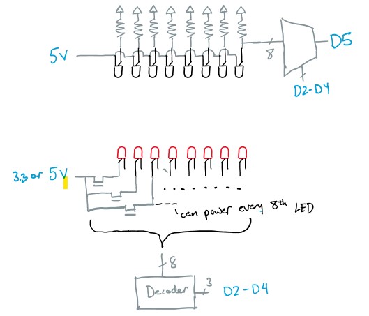
Towards the beginning of the week, we were still waiting for our parts to arrive. So, I started off by designing a PCB for the bottom side of our frame, which contains an array of 56 IR LEDs. The LEDs are turned on in groups of 4, where every 14th diode is turned on at the same time. We use two 3:8 decoders (only using 7 outputs from each) to turn on a power MOSFET that allows current to flow through the correct set of LEDs. On the far right-hand side, we have allocated space for through-holes for I/O and power supply from the external Arduino.
Shown below are, from top to bottom, an overhead, an underside, and a 3D view of the PCB.


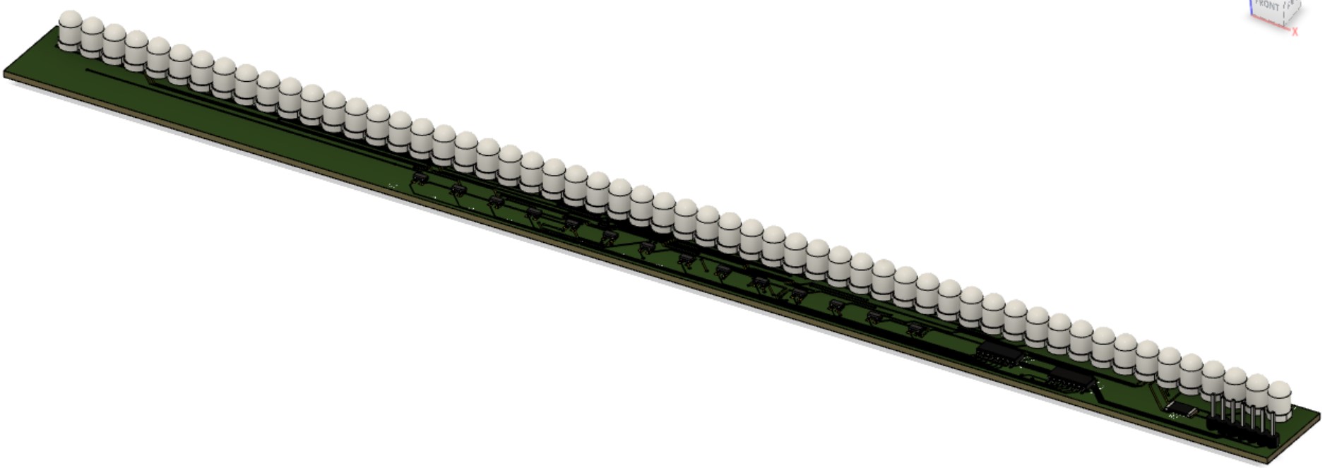 Edits may be made to add a ground plane. For our purposes, we won’t actually be inserting header pins and the LEDs will be oriented parallel to the PCB surface. We have yet to decide which side of the PCB we want the LEDs to protrude from.
When the parts arrived, the next step was to create one “segment” of our LED-Photodiode array. This involved creating an array of just 7 LEDs/Photodiodes and using only one decoder and one mux to select the correct inputs. The breadboarded circuit is shown below (emitters on top, photodiodes on bottom):
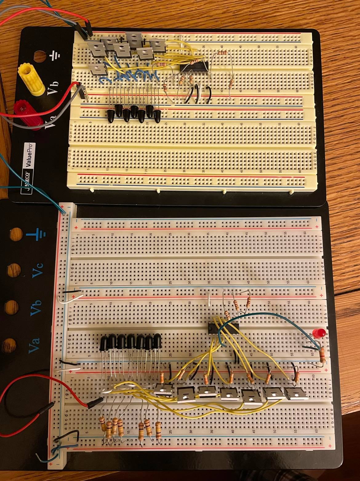
Throughout the verification of this circuit, there was one issue. Initially, the cathodes of the photodiodes were connected directly to the inputs of the multiplexer. However, there was unusual behavior when the light was blocked from entering the diode; for a still-unknown reason, instead of the voltage dropping to near-zero as expected, the voltage at this node would settle around 1.7 V. The voltage would still drop to 0 when not connected to the mux input. Fortunately, I had extra MOSFETs on hand, so I used these as buffers between the photodiodes and the mux inputs. This method removed the unusual 1.7 V at this node.
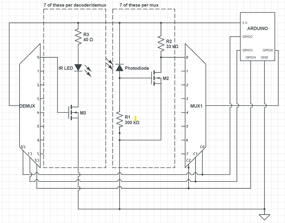
Below is a schematic of the above image, with repetitive elements removed:
Darwin Torres’ Status Report for 2/12/22
This week, I conducted research on how to interface with Windows to register our screen taps as mouse clicks. I have begun exploring different Python libraries and have narrowed down our choices to the following:
- pywin32
- PyAutoGUI
- mouse
As of right now, the main focus is to create demos to test each library and compare their performance, ease-of-use, and compatibility. Originally, I was going to create a simulation to test different configurations of our original analog design, but as we have updated our approach, this was no longer necessary, which allowed me to get ahead of schedule and move to this step. This weekend, in addition to developing the demos for each library, I plan to create an interface that would allow us to switch between each library, allowing for easier integration with my team’s code as we test out our screen control software and decide on which library is best.
Team Status Report for 2/12
Overall, we feel that we made significant progress on our project this week. The most important update is that we switched from an analog approach for determining finger position to a digital one. This change affords us several advantages; for one, it eliminates the need for a preliminary simulation, giving us at least an extra week of slack. Additionally, it removes a lot of the complexity of an analog approach, as digital detection will be far more immune to noise. The largest drawback of this approach is that it is more brute-force than the analog, and we will need far more diodes, which could provide some challenges as to how we package the circuit into a limited form factor. However, we think the pros significantly outweigh the cons, as the digital implementation is less risky in the long run. Our block diagram from the initial proposal remains largely unchanged, since our initial idea was also a digital approach.
We have identified two risks that could significantly affect the outcome of the project. The first is that we have limited space on the bottom edge of the laptop to place the hardware. Before switching to the digital approach, this was not a concern since the hardware would have only been on two edges, but it now needs to be on four edges since we are creating a 2D grid. For the laptop we plan to design the product for, there is currently an inch of vertical space below the screen for the hardware to be placed, so we think it is possible that this is sufficient. However, since it is not a guarantee, our current plan would be to build outwards towards the keys if we need more space. With the shift of our schedule, we should have more time to focus on the design of the frame, so this hopefully help mitigate the risk. A second risk we have identified is that the cost of the PCBs may put us over our budget. With our new approach, we have decided that PCBs are probably necessary in order to hold the hardware components in place. We currently do not have a specific estimate of how much this will cost, but we our planning to figure this out in the next week. As a worst case scenario, we have decided that we could have a 2D touch grid on the side of the laptop if we become affected by these risks.
Updated Schedule:

Matthew Kuczynski’s Status Report for 2/12
This week I have been working on researching, testing, and prototyping the Python-Arduino interface for our project. Since we plan on controlling the screen functionality with Python, this interface is necessary in order to communicate the digital readings from the Arduino so that finger position can be determined. Additionally, we want to use Python to set the digital pins going into the decoder (see Matt S.’s diagram).
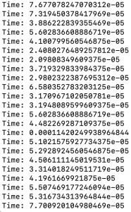
The most important part of my work this week was determining which platform/library was most suitable for our needs. Through my research, I determined the best interfaces were PySerial using Anaconda Prompt or similar, and pyFirmata. In the end, I found pyFirmata to be the best option because it is easy to use and felt more specific to Arduino in my opinion. The most important factor that I considered was if the interface would be fast enough to toggle through all of the combinations that we need. To do this, I tested how fast I could perform the standard Blink function on the Arduino by toggling digital pin 13 on and off as quickly as possible in a loop and recording the time that it took. A subset of the values that were recorded is included in the screenshot below. As you can see, the task usually took under 0.1 ms, although sometimes it took between 0.1-0.2 ms. Regardless, this should easily be fast enough since we are targeting a reading every 150 ms, and there will likely be less than 20 combinations per reading required in the end. This should provide sufficient time for the other calculations to be performed in each cycle. Finally, I was able to develop a small script that cycled through the combinations of D2-D4 pins that we plan to use (for now), as well as read from the D5 pin.
Overall, I am somewhat ahead of schedule on my tasks since we no longer deemed the simulation task to be necessary due to our switch from an analog approach to a digital one. We plan to adjust the Gantt chart to account for this, which will hopefully make our reach goal of multi-finger functionality more realistic.
Next week, I hope to combine my work with Darwin’s work in order to begin creating a Python code base for our project. Additionally, we hope to set up a basic physical circuit once our parts come in, so I will try to incorporate my work from this week into that.
Matt Shen’s Status Report for 2/12/22
For this week, my main task was circuit design and product purchasing based on the design.
List of components so far:
- IR Photodiode, 5mm-wide
- IR LED, 5mm-wide
- one with 6° viewing angle, 300 mW/sr
- another with 10° viewing angle, 550 mW/sr
- 3:8 Decoder, active-high
- 8:1 Multiplexer
- Power MOSFET, N-type
- Arduino Mega
Resistors are also shown below, but the ideal values for the design are yet to be determined. The diodes in black are photodiodes and in red are the IR LEDs. For the array of photodiodes, the cathodes are attached to the 5V pin of the Arduino. The anodes are each equipped with a pull-down resistor; each of these nodes is also hooked up to a Multiplexer’s input ports. The multiplexer then feeds either a high or low signal to an Arduino’s read pin. The photodiode being read from is selected by control pins from the Arduino. One potential issue that could arise from this design involves a limitation of the mux; with a VIL & VIH of 0.8 V & 2.0 V respectively, any values in the range of 0.8-2.0 V could cause errors. If this proves to be an issue in our breadboard tests, our first plan of action would be to add a single-MOSFET buffer in between each PDN and the Multiplexer.
For the LED array, we will use the same control pins for the mux to control the decoder. This decoder will instruct a power MOSFET to turn on its LEDs. We will also need resistors (not shown) for current limiting. For our diodes to work as desired, we need 100mA of current through them. In order to conserve power, we will try to have pairs of LEDs stacked on one another if the drain-source voltage of the MOSFET and on voltages of the LEDs permit enough headroom.
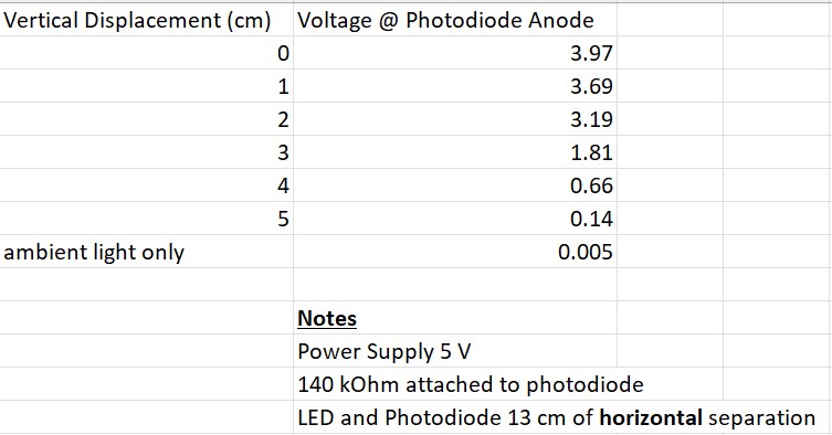
Finally, I also ran some tests this week to get a sense of how neighboring LEDs might interfere with light detection. These tests were done with a random IR photodiode, so we won’t put too much weight on them. We used the aforementioned 6° LED as well.
With regards to the timeline, I accomplished everything as was planned for this week, but nothing more. However, since our new implementation idea removes the need for a software simulation, I think we are slightly ahead of schedule. For next week, if we can get the parts before the next status update, it would be ideal to layout the circuit shown above and get it to interface with a Python-controlled Arduino. In the meantime, I will begin designing a PCB to get a sense of how much space our implementation will need.
Project Proposal Presentation Slides
Project Introduction
For our project, we intend to design a frame for a laptop that would give it touch screen compatibility. Our goal is to make it accurate enough and with sufficiently low latency for tasks such as drawing and website navigation. At a minimum, we would want our device to work with single-finger strokes. From there, we hope to integrate 2 and 3 finger gestures. This would allow us to design features such as programmable 3-finger gestures. For example, a 3-finger upstroke could open a certain app with ease. Such functionality would set apart our product from any similar one on the market.