Alvin’s Status Report- 3/27/21

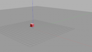
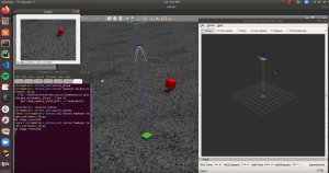
These past two weeks, I have built a functional launch sequence for the drone and verified its behavior in simulation. This sequence begins with arming the drone and having it takeoff to a set altitude of 3.2 meters (arbitrarily chosen for now)  using high level position commands (send desired position, drone’s flight controller handles orientation). The drone then switches to a lower-level control output of desired roll, pitch, and yaw to allow for more dynamic maneuvers.

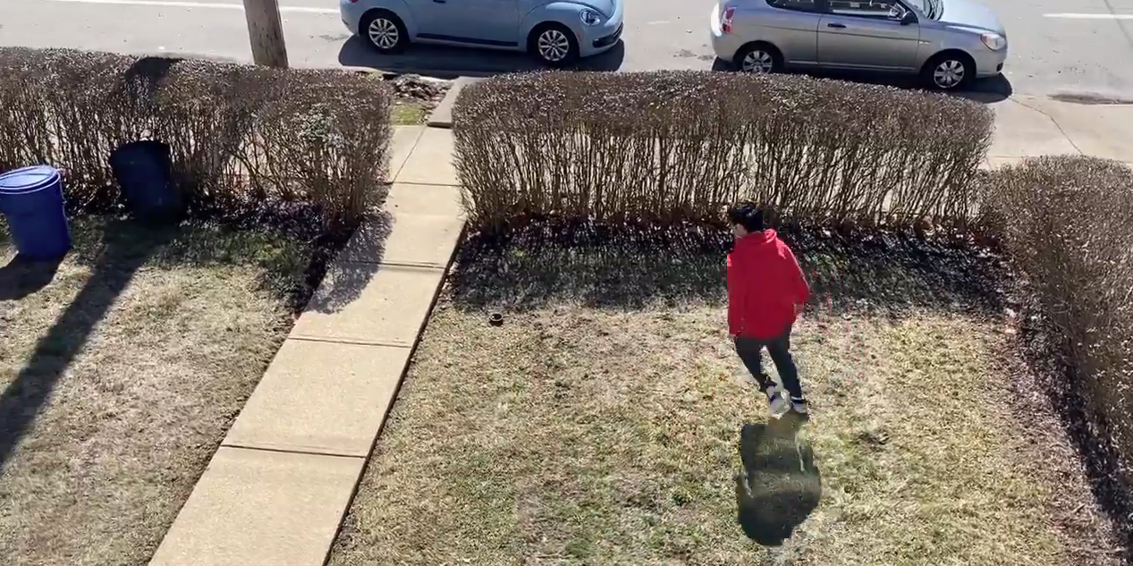
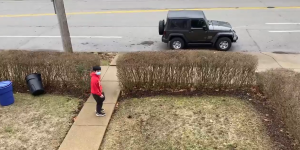
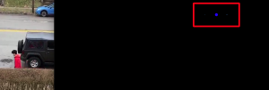
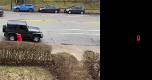
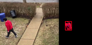
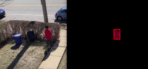
In addition, I have spent this last week implementing the transformation from 2D target pixel location to estimated 3D position in the world. This involves a combination of back-projection (transforming 2D pixel location into 3D position with respect to the camera) and intersecting a ray with the ground plane. More details can be found on this document: https://drive.google.com/file/d/1Tc6eirIluif-NBqA5EThOGmiCBtPO4DY/view?usp=sharing

Full results can be seen in this video: https://drive.google.com/file/d/1Tc6eirIluif-NBqA5EThOGmiCBtPO4DY/view?usp=sharing

For next week, now that I have 3D target position, I can work on generating 3D trajectories for the drone to follow so that it keeps the camera fixed on the target as much as possible (our objective function). I will first make a very simple baseline planner and stress-test the system so it is ready for physical testing next week.

Team’s Status Report 3/27/21

This week, our tasks were more related to integration, but still independent. Vedant and Sid were able to integrate target detection and state estimation and demonstrated impressive smoothing of the target location in 2D pixel space. Vedant also focused heavily on debugging issues with our new camera on the software side, while Sid developed CAD parts to attach this specific camera and other sensors to the drone. Alvin integrated both Vedant and Sid’s target detection and state estimation pipelines into a functional 2D to 3D target state estimation.

Our stretch goal was to begin physical testing this week, but we will push this to next week since we have faced unexpectedly long lead times for the 3D printing and connection issues with the camera. Once we can integrate all this hardware with the drone, we will begin physical testing.

Siddesh’s Status Report- 3/27/2021

For these weeks, I first started the CAD design process for the drone mounts. I had to design a mount which could be attached to the underside of the drone and house the Raspberry Pi, sensors for the drone (a LIDAR and a PX4Flow camera) and our camera for taking video. The camera position had to be adjustable so that we could modify the angle between test flights and figure out which is optimal. In addition, I had to make sure there was enough clearance for each of the ports on the sensors / Pi and that there was ample room for the wires connecting them. The .stl files are in the shared folder. Here is a picture of a mockup assembly of the mount attached to the underside of the drone:

After asserting the design seemed to work in the assembly, I scheduled the parts to be printed (along with a few other drone guards we found online). The parts were successfully printed and I started the assembly:

In addition to this, I modified the state estimation algorithm to handle asynchronous datapoints. Rather than assume that updates to the drone’s state and the target’s detected position come together at a set fps, I modified the algorithm to handle asynchronous updates that are tagged with the timestep they were sent out. Since the algorithm requires the drone and target updates simultaneously, when one is received without the other, I predicted what the state of the other would be given its last known state and the delta t. Using this, the algorithm then updates its model of the target’s/drone’s movement.

Finally, I also helped Vedant try and get the camera working with the Raspberry Pi 3. We figured out that the kernel version of the Raspberry Pi 3 did not support the IMX477 camera and even though we tried an experimental way to update the 3’s kernel, we eventually decided we needed to get a Raspberry Pi 4 instead since this experimental update caused the 3 to stop booting.

For next week, I intend to start integration with the team. We will finish assembling the drone mount and I will help create the main function on the TX1 that integrates my state estimator and Vedant’s target detection. After this, we will test the communication between the TX1 and RPi and hopefully try a few test flights.

Vedant’s Status Report 3/27/21

This week most of the time was spent debugging the camera with the Raspberry Pi 3. The camera doesn’t capture the image properly:

This is suppose to be a white ceiling. From extensive debugging, we figured out that a Raspberry Pi 4 will be necessary as the camera needs kernel 5.4. We tried updating the kernel to 5.4 with Raspberry pi 3 but that was not stable. We tried many libraries from Arducam (https://github.com/ArduCAM/MIPI_Camera/tree/master/RPI) and this other than raspistill. None of these solved the problem. Therefore, we have ordered a Pi 4 and the necessary cables. Also I got the wearable display working with the TX1, here is an image of our test video shown on the wearable display:


I am not behind schedule and next week the plan will be to get the camera working with raspberry pi 4 and stream the video captured to the tx1 using ROS so that I can integrate my object detection code.

Siddesh’s Status Report- 3/13/21

This week I first sent test videos to Vedant for him to test out his target identification from a roughly 20′ elevation and under a variety of lighting conditions / target motion patterns. I then spent my full effort working on target state estimation. The purpose of target state estimation is to be able to model the target’s current motion at predict their future path. We can’t just identify the center of our target every frame and tell the drone “go to this position”. For one, the computer vision is not guaranteed to be perfect, and the center may not be exactly at the target’s center. Being “reactive” like this would likely create very jerky motion. More importantly, the drone’s flight controller needs to plan out movement at least a second or more into the future, so it would be impossible to simply receive a frame of data and react instantaneously. Thus, the goal is to smooth out the frame-by-frame target data outputted by the CV algorithm and create a model for the user’s current motion that would enable us to predict their motion at least a short while into the future.

In order to do this, I had to first create a test environment where I could generate a “random motion” and simulate the input that would be provided to the state estimator. To do this, I generated a random polynomial to model the target’s x and y coordinates as a function of time. Then, at a specified fps, I would sample the target’s current coordinators and add some Gaussian noise to mimic inaccuracies in the target detection before sending these samples to the state estimator.

For the state estimator, I implemented a Kalman filter from scratch where at each point in time we model 6 things: the target’s x/y position, x/y velocity and x/y acceleration. Every time the estimator receives a new “sample”, it probabilistically updates these 6 quantities within current model of the target’s motion. I then simulated how a drone would move based on the x/y velocities of the estimator’s modeled motion. For some reason, I can’t upload .mp4 files to WordPress but an example of this simulation can be found in StateEstimation1.mp4 in the Google Drive folder. (the black points are the target’s actual motion, the red points are the noisy samples that are sent to the estimator and the green points are how the drone would move based on the estimator output).

The Kalman filter approach seemed to be able to successfully smooth out the noise from the red points, and enable the drone to follow the target smoothly and relatively accurately.  The next step was to simulate this with a more “human” motion rather than a contrived polynomial. The “human” motion has more gradual changes in acceleration and obeys a speed limit (10 mph). In addition to this, I let the target wander around infinitely and centered the screen to the drone position to get an idea of how a video feed coming from the drone would look. An example of this is in StateEstimation2.mp4

After tweaking the parameters, the results seemed very encouraging. The drone was able to follow a smooth motion plan despite the noisy data that was being inputted and the target generally stayed very close to the center of the frame in the simulation. For next week, I plan to make a minor change to the estimator in order to enable it to receive asynchronous samples (rather than at a fixed interval). In addition, I plan to test out the state estimator on Vedant’s results from target identification on the real-life video. Moreover, while I wasn’t able to design a mount to attach the camera and RPi to the drone (since the camera hadn’t shipped yet), I aim to get that finished next week.


Alvin – 3/13/21

Earlier this week, I presented our design review, which was focused on the specifics of implementation and testing that would help us meet our metrics/requirements for a successful project.

On the project implementation side, I focused on connecting the simulator to the drone’s flight controller API, and was able to send motion commands to the drone and watch the results in simulation. This will be useful since any code testing in this simulation can be directly applied onto the physical drone with no change, the only tweak will be the communication port used.

Unfortunately, our old simulator of choice (Airsim) proved incompatible with the flight controller API. I was able to get the simulator and the controller’s Software In the Loop (SITL) framework to communicate  half of the time, but the other half of the time, the simulator would randomly crash with no clear reason. After extensive search through online forums, it was clear that Airsim was still addressing this bug and no solution was available, so I decided to just avoid the trouble and work with a more stable simulator, Gazebo. Shown in the  picture is a colored cube that we will treat as the simulated human target to test the integration of motion planning and target tracking.

Next week, our priority is to begin integration and get the drone up in the air with target tracking. In this case, I will focus on making sure we have a well-tested procedure for arming the drone, letting it takeoff to a height of 20 feet, and implementing a very basic motion plan that will just follow attempt to follow the 2D direction of the target.

Team’s Status Report 3/13/21

We continued to work on our individual tasks this week. We have a completed computer vision algorithm that has been tested (still need to run on TX1 though), and state estimation algorithm. Further, we have the drone simulator working which allows us to test the state estimation algorithm first to see how the drone reacts before we physically fly it.

Next week, we plan to test the state estimation algorithm with the test video used for the computer vision. We also plan on focusing on the external interfaces like designing the camera mounting and getting the drone to fly an arbitrary path in simulation and physically. All these targets will help us get closer to integrating the drone with the computer vision and state estimation algorithm. We also plan on making the button circuitry for the wearable.

Vedant’s Status Report 3/13/21

This week I worked on testing the computer vision algorithm I implemented last week. The test setup was  a stationary 12 MP camera (to simulate the one we will use) at an approximate height of 20ft recording a person walking and running wearing a red hoodie (our target) under sunny and cloudy environment:

Sunny condition

Cloudy condition

The algorithm did not work well for the cloudy condition (where the target is walking) as it picked up the blue trash can and car that was parked:


Note the blue dot in the center of the red bounding box is the center of the tracked object. In the first picture, the algorithm switches from tracking the person to tracking the blue car parked

Under the sunny conditions (where the target is jogging), the algorithm was perfect in tracking the person:

As seen from the above picture, the blue car and garbage can are filtered out.

To better the algorithm for not well lit conditions, I used rgb filtering rather than converting to hsv space:

In the first picture, the new algorithm is still tracking the person and has filtered out the blue vehicle in the background. In the second picture, the new algorithm also filters out the blue garbage can unlike the old algorithm.

The new algorithm also worked in the sunny conditions:

Therefore, the algorithm using rgb filtering will be used. I also calculated the x, y position of the center of the target’s frame which will be used by Sid for his sate estimation algorithm.


We are on track with our schedule. Next week, I will shift my focus on developing the circuitry for the buttons, and if I get the camera we ordered, I will run the computer vision on the TX1.

Team Status Report- 3/6/21

This week, we started setting up the Jetson TX1. We tried setting up the TX1 and installing the SDK on a Windows laptop but this didn’t end up working due to using WSL instead of an actual Ubuntu OS. So, we met up at lab to download and configure Jetpack and install ROS on the Jetpack. During the process, we ran out of space on the internal memory. and had to research methods for copying over flash memory to an SD card and booting the Jetson from an external SD card. In addition. we started working on the color filtering and blob detection for identification of targets using a red Microsoft t-shirt as an identifier. In addition, we set up the drone flight controller and calibrated the sensors. Finally, we designed a case for the TX1 to be 3d-printed and worked on the design presentation.

For next week, we will continue working on the target identification, using test video we capture from a 2-story building to simulate aerial video from 20 feet up. In addition, we will start to work on preliminary target state estimation using handcrafted test data and design a part to mount the camera to the drone. We will also install the necessary communication APIs on the RPi and set up an initial software pipeline for the motion planning.

Alvin 3/6/21

I met up with Sid to help install the Jetpack SDK on the TX1 as well as install ROS, but weren’t able to finish the full setup due to a memory shortage. I also helped build the design review presentation for this upcoming week.

This week was extremely busy for me, and as a result I didn’t accomplish the goals I set last week: namely setting up a software pipeline for the motion planning and actually testing on the simulator. What I did instead was set up the drone’s flight controller and double-check that my existing drone hardware was all ready for use. The drone and flight controller already contain the bare minimum sensors to enable autonomous mode:

  • gyroscope
  • accelerometer
  • magnetometer (compass)
  • barometer
  • GPS

I used the open-source QGroundControl software to calibrate these sensors. The accelerometer calibration is shown as an example below:

I also wired up other sensors to the drone’s flight controller:

  • downward-facing Optical Flow camera
  • downward-facing Lidar Lite range-finder

This next week, I will finish installing the communication APIs on our Raspberry Pi to communicate with the flight controller and verify its success with ROS by sending an “Arm” command to the drone. I will also finish last week’s task to set up an initial software pipeline for the motion planning.