Siddesh’s Status Report- 4/24/2021

(This status report covers the last two weeks since no reports were due last week).

At the start of two weeks ago, we all met in the lab but were struggling to get the drone flying and our camera image was entirely red tinted. Apparently, the auto white balance on the camera was completely screwed up. I created a main Python function on the Jetson that would automatically receive the images streamed by the Raspberry Pi, run the object detection and display the results on the monitor screen. I modified the main function so we could manually send white balance values to the Raspberry Pi and have it change these values for the camera on the fly so we could adjust the white balance of the photos. Still, the image was extremely desaturated no matter what we tried.

Eventually, we decided to get a new camera (and a Wi-Fi radio we could hook up to the drone to receive error messages while attempting to fly). While waiting, Alvin and I tackled drone motion planning- each one of us using a separate approach. The idea behind drone motion planning is that we already have a target detection algorithm and a target state estimator that can model the future movement of the target. We now need to model the future movement of the drone and create a motion plan such that:

  1. The target stays close to center of frame.
  2. The drone doesn’t have to make extreme movements

For my approach, I created a 3D simulator that simulated the target’s motion, the drone’s motion (based on our motion plan) and the drone camera output (based on the camera’s internal matrix). The simulator is pictured here:

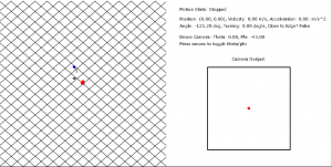
My approach to motion planning was to run optimization on an objective function, trying to minimize the following two quantities:

  1. The negative dot product between the unit vector of the camera orientation and the unit vector from drone to target. Basically, the higher the dot product, the closer the target is to center. Since this is a minimizer I took the negative dot product.
  2. A regularization term that aims to minimize the sum of the squared velocities in the drone’s motion plan (basically try and make the drone move as slowly as possible to accomplish our goals)

The relative proportions of these two can be tweaked. In our Google Drive folder, I’ve attached video of when we only try to minimize 1) and when we try to minimize both 1) and 2). The first case has more accurate tracking, but the drone’s movements are jerky and unrealistic. The second case has slightly less accurate tracking, but much smoother and achievable motion.

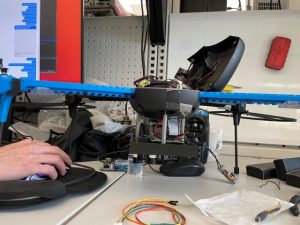
Finally, we received the new camera and Wi-Fi radio and began to set the groundwork for autonomous flight. First, we met in lab and actually got the drone to fly under manual control. We took test video, and to make things easier, I modified the main functions of the Jetson and the RPi so that the Jetson can send commands to the RPi that can handle events such as starting the camera or stopping the camera. I then modified the RPi’s config files so that the video streaming program would run at boot. This enabled us to easily start our video streaming. As soon as we connected the RPi to the drone’s battery it would start up the program headlessly, and then we could send it commands through the Jetson to start the video streaming.

After getting the drone to fly manually, I helped setup mavros on the RPi so we could connect via serial and finally start sending autonomous commands to the drone. Today, we were finally able to start sending basic autonomous commands to the drone and have it hover to a set position and remain there.

Siddesh’s Status Report- 4/10/21

This week I worked with the team to help the drone get up in the air in the lab. Unfortunately, we ran into a few setbacks during the process that we had to overcome. The first hurdle was that the Raspberry Pi 4 unexpectedly stopped working and gave us the “green light of death” where the green light consistently remained on rather than blinking as it was supposed to, and the Pi wouldn’t boot. I researched the issue, and there were a number of possible causes such as the SD card reader being faulty or a fuse tripping (which would take a few days to reset). I contacted various professors and organization, and eventually we were able to secure a replacement one from the RoboClub.

In addition, I worked with Alvin to get build the proper firmware to upload to the PixHawk flight controller in order to interface with the sensors, and to connect all the sensors together to the flight controller. There were again a few setbacks here, as the internal flight controller’s flash memory was too small to handle the firmware, and we had to constantly adjust the build ourselves and try and get rid of certain firmware features that we didn’t need in order to get the build to the right size. After a long while of tweaking, we were successfully able to upload the firmware successfully to the Pixhawk and setup the proper sensors and airframe.

I also worked with the group to try and test out how we would power the Raspberry Pi by using the LiPo battery on the drone as a power supply and sending it through a buck converter to regulate the voltage sent to the Pi. In addition, I helped with the testing of the camera to get a script that can automatically record video to an external flash drive, and successfully debugged an issue we had where when running the script from boot, the script would run before the OS had detected the external flash drive, leading to an error where the file location would not exist.

Tomorrow, we aim to get our drone flying successfully, as all the infrastructure for integration is finally in place. We plan on working on getting everything prepared for our demo, and going for our first test flights.

Siddesh’s Status Report- 4/3/2021

This week I worked on the assembly of the drone apparatus, the calibration of the sensors and the integration of the state estimator into the simulator.

First, I went into the lab with the group to gather hardware and assemble the sensors and camera onto the configurable mount we 3D-printed. I finished mounting all the sensors and the Raspberry Pi, tested the tolerances, and ensured we had enough space for all the wires and the ribbon cable. Here is a picture below:

I also modified the CAD design to include the entirety of the IRIS drone rather than just the bottom shell. This is important because in order to convert the 2D image coordinates to absolute 3D coordinates, we need to know the exact position and pose of the camera relative to the internal Pixhawk 3 flight controller. Thus, I also added a CAD model of the flight controller to the assembly in the correct position so we could properly measure the position and pose in order to calibrate the drone’s sensors. This final 3D assembly can be found as “Mount Assembly 2” in the Drone CAD subfolder of the shared team folder.

Finally, I worked with Alvin to integrate the state estimator into the simulator. First, I had to modify the state estimator to work with 3D absolute coordinates rather than 2D pixel coordinates relative to the position of the drone. In order to do this, I added a z position, velocity and acceleration to the internal state model and modified the transformation matrices accordingly to account for this change. I then debugged the estimator with Alvin as we integrated it into the simulator in order to track the simulated red cube across a variety of different motions. A demonstration of this can be found in kf_performance.mp4 in the share folder. The target red cube’s position is marked by the thin set of axes. It accelerates and decelerates in extreme bursts to simulate a worst case (physically impossible) target motion. The noisy measurements captured by the camera and target detection are modeled by the small, thicker set of axes. Finally, the smoothed out motion from the state estimator’s motion plan is modeled by the larger, thicker set of axes. While the motion plan drifts slightly when the target accelerates rapidly, it does a successful job of smoothing out the extremely abrupt motion of this cube.

For next week, I plan to work with the team to get the drone fully into flight. I plan to help Vedant write the scripts for ROS communication between the RPi and the TX1 and finish calibrating the drone’s internal flight sensors with Alvin.

Siddesh’s Status Report- 3/13/21

This week I first sent test videos to Vedant for him to test out his target identification from a roughly 20′ elevation and under a variety of lighting conditions / target motion patterns. I then spent my full effort working on target state estimation. The purpose of target state estimation is to be able to model the target’s current motion at predict their future path. We can’t just identify the center of our target every frame and tell the drone “go to this position”. For one, the computer vision is not guaranteed to be perfect, and the center may not be exactly at the target’s center. Being “reactive” like this would likely create very jerky motion. More importantly, the drone’s flight controller needs to plan out movement at least a second or more into the future, so it would be impossible to simply receive a frame of data and react instantaneously. Thus, the goal is to smooth out the frame-by-frame target data outputted by the CV algorithm and create a model for the user’s current motion that would enable us to predict their motion at least a short while into the future.

In order to do this, I had to first create a test environment where I could generate a “random motion” and simulate the input that would be provided to the state estimator. To do this, I generated a random polynomial to model the target’s x and y coordinates as a function of time. Then, at a specified fps, I would sample the target’s current coordinators and add some Gaussian noise to mimic inaccuracies in the target detection before sending these samples to the state estimator.

For the state estimator, I implemented a Kalman filter from scratch where at each point in time we model 6 things: the target’s x/y position, x/y velocity and x/y acceleration. Every time the estimator receives a new “sample”, it probabilistically updates these 6 quantities within current model of the target’s motion. I then simulated how a drone would move based on the x/y velocities of the estimator’s modeled motion. For some reason, I can’t upload .mp4 files to WordPress but an example of this simulation can be found in StateEstimation1.mp4 in the Google Drive folder. (the black points are the target’s actual motion, the red points are the noisy samples that are sent to the estimator and the green points are how the drone would move based on the estimator output).

The Kalman filter approach seemed to be able to successfully smooth out the noise from the red points, and enable the drone to follow the target smoothly and relatively accurately.  The next step was to simulate this with a more “human” motion rather than a contrived polynomial. The “human” motion has more gradual changes in acceleration and obeys a speed limit (10 mph). In addition to this, I let the target wander around infinitely and centered the screen to the drone position to get an idea of how a video feed coming from the drone would look. An example of this is in StateEstimation2.mp4

After tweaking the parameters, the results seemed very encouraging. The drone was able to follow a smooth motion plan despite the noisy data that was being inputted and the target generally stayed very close to the center of the frame in the simulation. For next week, I plan to make a minor change to the estimator in order to enable it to receive asynchronous samples (rather than at a fixed interval). In addition, I plan to test out the state estimator on Vedant’s results from target identification on the real-life video. Moreover, while I wasn’t able to design a mount to attach the camera and RPi to the drone (since the camera hadn’t shipped yet), I aim to get that finished next week.


Siddesh’s Status Report- 3/6/21

This week, I first started by setting up the Jetson TX1 and downloading the Jetpack SDK. I ran into an initial bottleneck because the host PC required Ubuntu 18.04 to run Nvidia’s SDKManager application. Since I owned a Windows laptop, I attempted to use WSL in order to run this application, however I encountered numerous problems such as WSL not being able to display graphical applications without downloading a separate X-server, Windows firewalls preventing redirection, and WSL being unable to recognize USB devices plugged into the laptop. Ultimately, after four hours of troubleshooting this and contacting Nvidia support, we decided that Alvin and I would meet up at HH1307 later in the week to complete this process using his laptop. We were able to download the Jetpack SDK to the TX1 and download/configure ROS for the TX1. However, when trying to install Python libraries such as PyTorch, we realized that the TX1 had run out of internal memory. We tried researching solutions and eventually found that we could reformat an SD card, copy the contents of the flash memory to this SD card and configure the TX1 to boot from the SD card rather than internal memory. We acquired the necessary tools for doing so and will do so tomorrow.

In addition to setting up the TX1, I finished designing a case for housing the TX1 while the user is carrying it. I created this case by modifying a template for a top case I found online and then creating a new backplate that can be screwed on to the back of the case with the TX1 being sandwiched in the middle. We plan on 3D printing this early next week. I also began to research methods for target state estimation and worked with the team to create the design review presentation.

Next week, I will begin to work on target state estimation using arbitrary frame by frame (x, y) and bounding box data that I will create myself for testing. In addition to this, I will begin designing the housing to mount the camera and the Raspberry Pi onto the drone.  Finally, I will also help provide test video to Vedant of targets with various different shirt colors walking outside, 20 feet below the camera so that he can figure out what colors are best detected in the outdoor lighting conditions.

Siddesh’s Status Report- 2/27/21

Last Sunday, our team finalized the Gantt Chart and schedule for the project. On Monday, I presented the proposal. After that, we worked together to divide up which components each of us would focus on researching for ordering. I researched batteries for powering the TX1 and concluded we should buy a 3S LiPo battery along with a charger, a charging bag and an XT-60 male to 2.5 mm barrel connector for connecting the battery to the TX1. In addition, I researched the type of camera we would need, using this calculator to figure out the width and height of the frame in feet given the camera’s focal length and distance to target. I found that a camera with a focal length around 4mm would give about a 20′ by 30′ frame when 20′ above the target. At a resolution of at least 720p, a back of the envelope calculation shows that this should provide enough pixels of the target for CV detection. n addition, the smaller focal length means that the camera itself is a lot more study.  Under these specifications, I found this camera that is meant to be connected to a Raspberry Pi, has the desired focal length and can provide 720p 60fps video (we only require 720p 30fps). Finally, in addition to researching these parts, I studied the datasheet of the TX1. I also downloaded Solidworks onto my computer and started learning how to use Solidworks for CAD design.

I wasn’t able to start testing the TX1 this week since I needed a monitor, keyboard and mouse (which I am acquiring today). Thus, for next week, I aim to fully set up the TX1 and create some sample programs (such as testing out Wi-Fi communication capability). I will also download and configure ROS on the TX1. In addition to this, I will start researching methods for performing target state estimation and begin the CAD process for the housing for the TX1, display and the camera / Raspberry Pi.

Siddesh’s Status Report- 2/20/21

I helped to write a new abstract for both our Bluetooth triangulation idea and our newly refined drone idea and looked up what specific technologies we could use for implementation. For the Bluetooth triangulation idea, I helped to identify SOCs that could support direction finding and helped email a PhD student for more information on this. For the drone idea, I helped solidify the requirements for our MVP and decide what the exact deliverables for our project were. After we decided on our final idea, I worked with the team to figure out how to divide the tasks and planned when we wanted to get each task done. I also worked on the presentation with the team. For next week, I will begin familiarizing myself with computer vision techniques for identifying people, and help create the schedule. I will also figure out what parts to order with the rest of the team.