The biggest risk right now is an incompatibility between the physical circuit and the software implementation in the final day of product implementation before the presentation is due. A difficulty in this aspect could prove to be a costly delay. This has been mitigated mostly by a good amount of software level verification from both Joy and Yuyi.
No changes in schedule have been made so far as the dominating factor this week is the presentation.
This week, I spent most of my time advising Kenny on the assembly and testing of the mount electronics. Soldering the surface mount components proved to be unexpectedly challenging, and we had to get around multimeter reliability issues, inadequate desoldering equipment, and solder-related issues (Kenny had inadvertently ordered lead-free solder paste for use with the SMD components, which meant that he had to deal with the intrinsic difficulties of using lead-free vs. leaded solder as explained here: http://www.pcboardrework.com/difference-between-lead-and-lead-free-solder/). In addition to advising him on his difficulties, I also laid out procedures that he could apply to ensure the functionality of the mount electronics, ranging from the usage of the laser diodes intended for the test setup as makeshift current indicators for the mount’s unipolar motor driver PCB to the application of an ammeter (in conjunction with a large 10W resistor) for safely testing the NEMA 17 motor drivers’ H-bridges.
Given that the majority of my contribution is complete, I’m reasonably on schedule.
Tomorrow, we will conduct experiments to characterize the tradeoffs inherent in our design. These include the following:
This week was mostly spent on getting the last few particulars of physical assembly done. Tomorrow (Sunday 26 2020) will mostly be spent on getting data and video compiled for the upcoming presentation. As of Saturday 4/25/2020 at 9:16 pm the progress on each individual physical part is as follows:
On top of that a few visual aids have been set up for debugging and demonstration purposes:
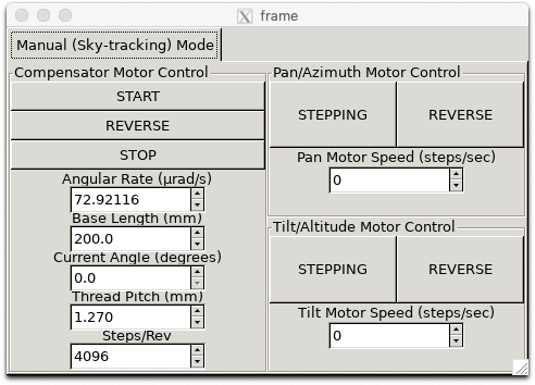
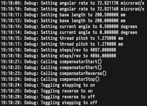
I was able to verify that CV code compiles on the Pi and works with the motor controllers and libgphoto2 camera input. I wrote a GUI app (attached is a screenshot) for the motor controllers and fixed some bugs that my teammates pointed out to me. I haven’t integrated the CV code into the GUI app yet, so I am behind on that. Next week we have our final presentation, and the week after that we have the final demo, so I will spend next week working on those with my teammates, working on integrating the CV code into the GUI, and working on any last-minute software improvements.
The principal risk to the completion of the project at this late stage is the slowness with which assembly of the mount is proceeding. We also need to finish addressing the integration of the CV routines Joy has written with the mount hardware, such as the libgphoto2 interface to the mount camera. Given the remote nature of most of the remaining work, the only recourse seems to be the scheduling of more frequent status meetings until the dates of the in-lab demo and the final presentation. We’ve also created a Google document to list goals for each day of this final week.
No changes to the schedule or system design have been made.
Here’s a picture of a partially assembled motor controller PCB:
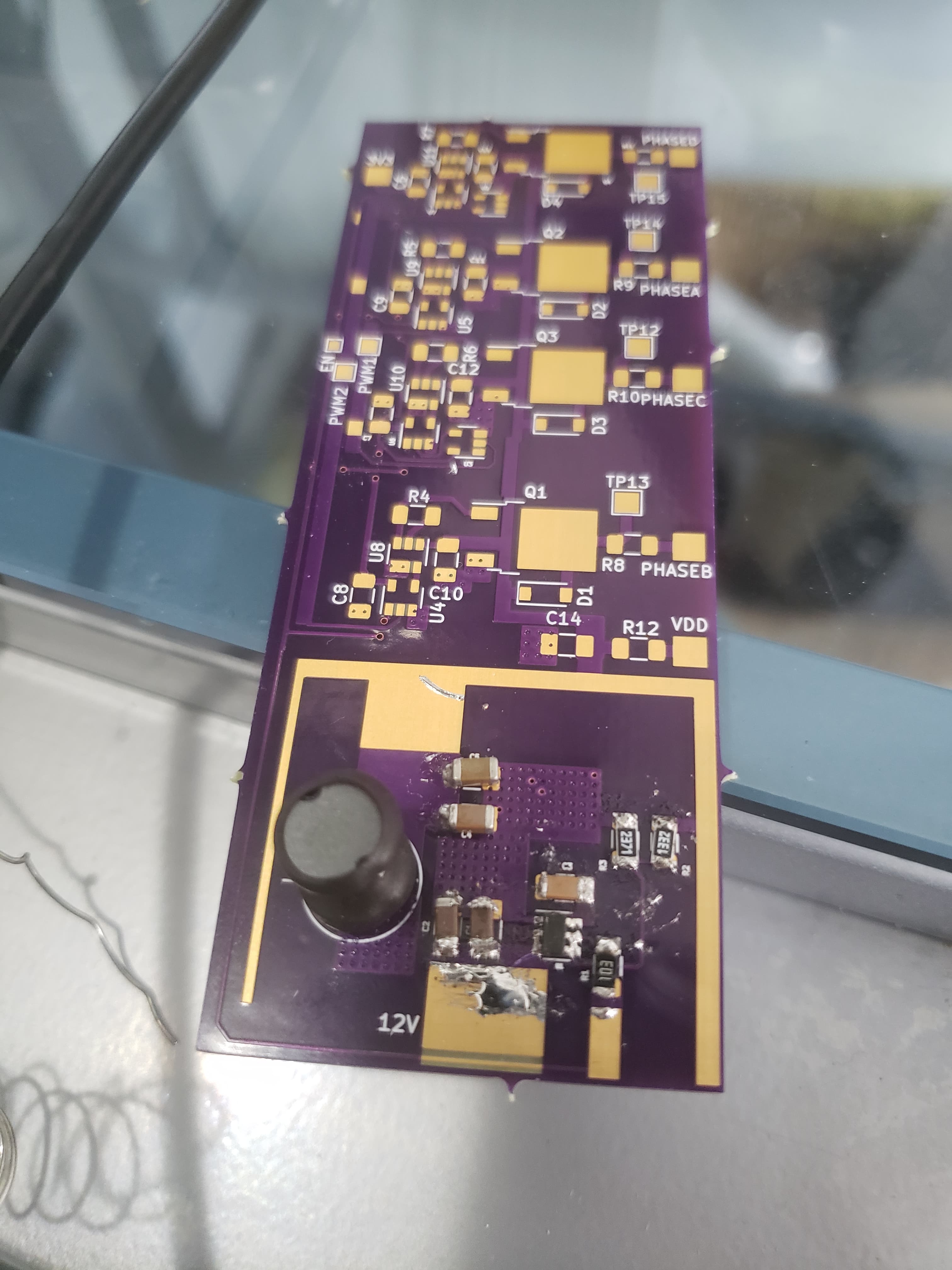
Feeding power to the 12V input of the buck converter that’s assembled on the bottom of the PCB causes the expected 5V to appear at the VDD pad, which is a promising result given the difficulty of soldering the SMD components. Tests of the remainder of the board (which composes the actual motor controller) should occur tomorrow afternoon at the latest.
This week, I mostly assisted Joy and Kenny with the integration of the mount electronics with the remainder of the mount. In Kenny’s case, this was just a matter of checking in on his progress with assembling the electronics (both on PCB and breadboard). In Joy’s case, this meant going over the meaning of the logic inputs of the unipolar and bipolar motor drivers, and the sequences in which they were supposed to be driven to effect a full-step sequence.
I also checked Joy’s motor driver code against the full-step sequences described online for bipolar and unipolar stepper motors, and wrote test cases in motor_driver/main.cpp. If all goes smoothly, main.cpp should cause one of the unipolar Digikey motors to rotate 3 times before reversing to the original position at 1 RPM, while setting one of the bipolar NEMA 17 motors to rotate at 60 RPM for a minute before turning off.
As a debugging aid, I also drew logic diagrams for the bipolar motor driver inputs that indicate the direction of current flow for different values of EN and PWM and labeled full-step sequence diagrams:
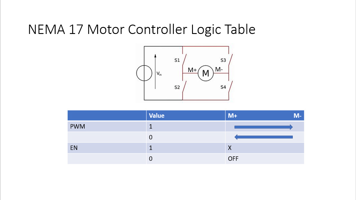
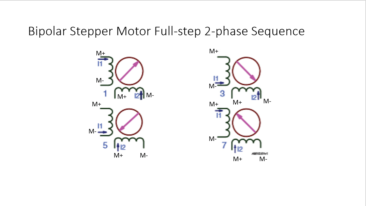
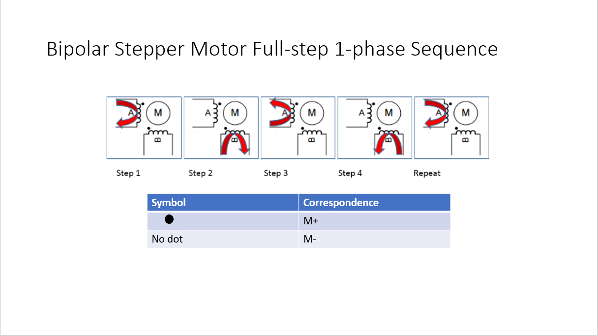
I felt that it was unnecessary to do the same for the unipolar motor driver, due to the lower complexity of the stepping sequence.
Thus far, I’m on track relative to the schedule. Next week, I need to start working on preparing materials for the demo video that cover my contribution to the project, while continuing to advise Kenny on the assembly and testing of the motor drivers. Since the vast majority of my tasks are complete, I will also spend some time working on the final report for the project.
This week I finished up the code for controlling the unipolar and bipolar stepper motors. It consists of two classes, one for controlling unipolar stepper motors and one for controlling bipolar stepper motors. The code I wrote uses std::thread to set the relevant GPIO pins in a loop so that multiple motors can be controlled at once. It also implements step-counting for tracking the number of revolutions taken. The GPIO library used was WiringPi. I found this article very helpful.
Next week, I will be working on checking that the CV code can run on the Pi, allowing the CV to use camera input, and hooking it up to motor control. I will also be working with Kenny to modify his polar alignment code from earlier in the semester to work with the rest of the system.
My tasks for the week:
What I have from this week:
Two squarewaves in quadrature from the GPIO pins of the Pi, at a much lower frequency than necessary for the PWM signals for motor control. (I don’t have an oscilloscope, although I might be able to hack something together with an Arduino, if I can find one) These are for the unipolar stepper motors for the compensator and test setup.
I lost some time trying to set up the Pi, and I’m also working on porting the code from the last few weeks to the Pi.
My progress: I’m behind on the motor controller interface. I expected to have more done.
Next week: More work on the motor controller interface.
System Changes:
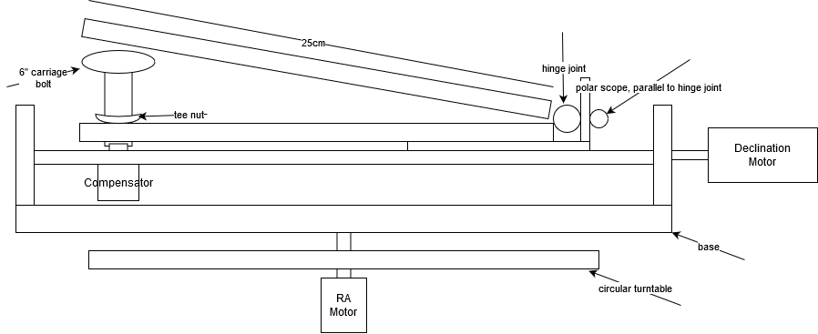
The main changes done this week basically break down to design changes to accommodate parts trickling in over time. Most of this is adapting the previous eq aligning design to the new barn door tracker. After receiving the universal stepper motor couplers I should be able to assemble the top portion of the diagram above with the exception of the motors since I do not have the pcb’s yet and I would like to thoroughly test them before placing them into the mount. Some things to point out in the diagram below include:
Progress has also been done in adapting logging for the Arduino. Getting the logger right now outputs to csv in real-time via a python script.
Risks:
Unfortunately, the arrival of the incorrect board types set back demo-readiness a fair bit, hopefully once the new boards arrived the new design will be ready for it. So that’s a risk that we could face.