Yuyi Shen’s Status Update for March 14 2020

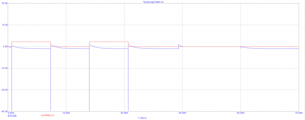
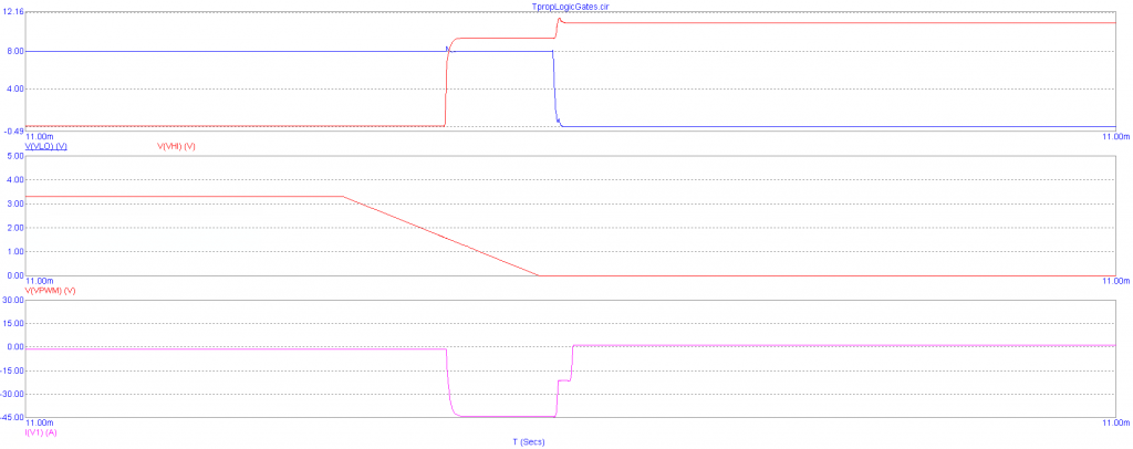
This week, I resolved the shoot-through issues that the motor controller board was experiencing. This was mainly done by increasing the value of the H-bridge gate resistors until the MOSFET turn-on times were significantly longer than the turn-off times, generating dead-time in which neither MOSFET on a single side of an H-bridge is on. An acceptable shoot-through current spike specification was calculated by assuming that the shoot-through current was relatively constant for the duration of the spike (which was roughly 1 us in transient simulation), and relating the resultant flow of charge to a drop in the voltage of the H-bridge power supply output capacitors. By setting this maximal voltage drop to 0.03 V (so that the output capacitors retained 99% of the nominal output voltage after a shoot-through spike), I calculated that a maximum shoot-through current of 1.2 A for 1 us was satisfactory for the motor controller design. This maximum shoot-through current specification was found to correspond to a gate resistor value of 4152 Ohms in simulation. Setting the gate resistor to 4.22 kOhms (the nearest available value in Digikey) produced the following waveforms:

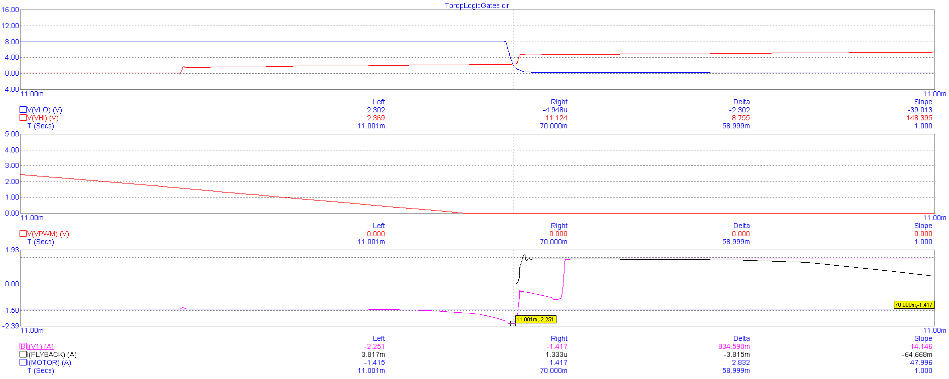
As can be seen from the pink waveform in the bottom-most plot, this value of gate resistor results in a shoot-through current spike of 2.251 A. From the waveforms of the hi-side and lo-side MOSFET gate voltages shown in the upper-most plot, we can see that the turn-on time (the red waveform) is much longer than the turn-off time (shown in the sharp edge of the blue waveform). Therefore, the circuit is operating properly for this value of gate-resistor.

Re-simulating for the circuit propagation delay, we find that the tplh of the PWM input is now 1.127 ms, while the tphl is 1.1 ms. Since this is much less than the period with which we plan to switch the motors, the gate resistors clearly do not overly impact circuit performance.

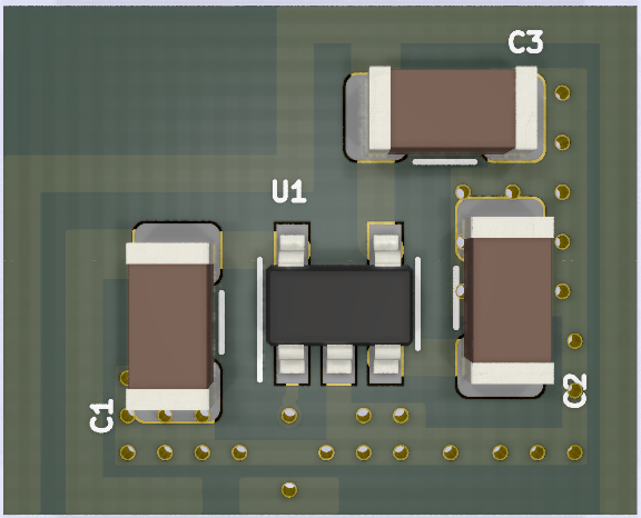
After making this refinement to the motor controller circuit, I generated a preliminary layout on PCB:

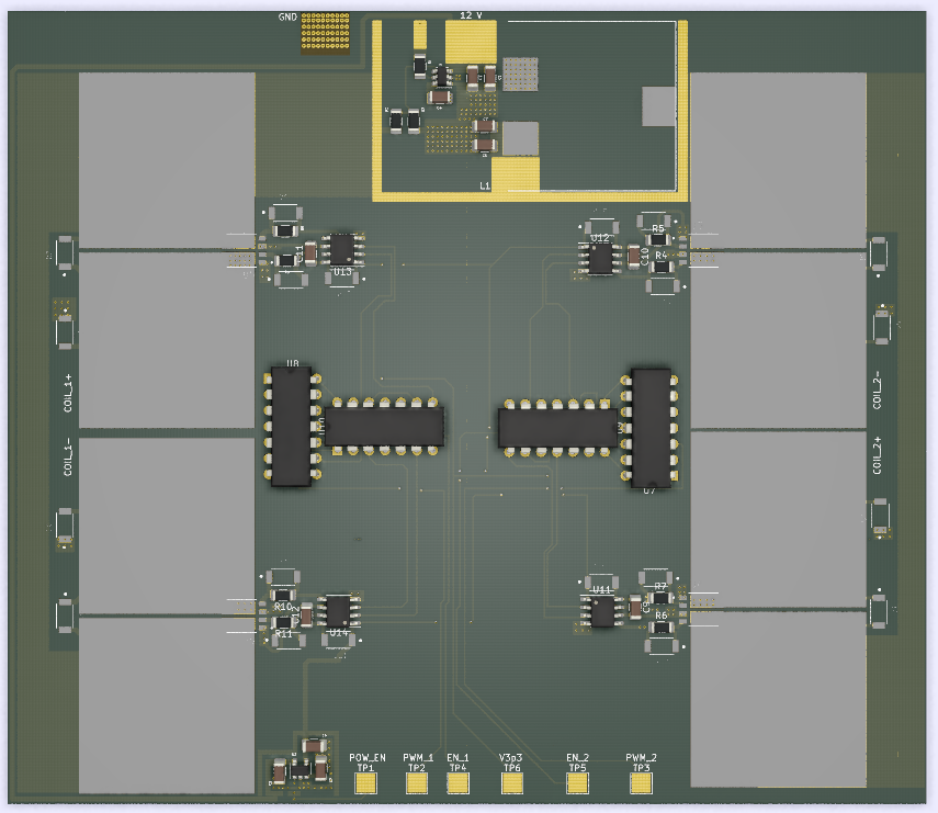
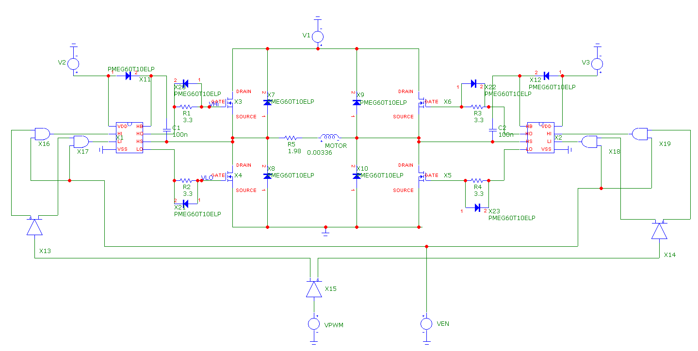
The 8V and 3V supply modules were pasted in from their respective layout files, while the remainder of the board was laid out in accordance with http://www.ti.com/lit/an/slva959a/slva959a.pdf. All that’s left is to place additional charge-storage capacitors at the power nodes. Here’s the updated schematic: schematic

I’m slightly behind schedule on this. I was supposed to complete the layout process earlier in the week, but ended up taking longer than expected. However, assuming that we follow the current schedule, all that’s left is to make the aforementioned revisions and perform a design review before ordering the board.

I’m uncertain as to what I should aim to complete next week. CMU’s recent move to remote instruction in light of the recent pandemic means that there will be substantial changes to the plan for capstone moving forward, and it’s unclear if there’ll still be a project component to this class.

Yuyi Shen’s Status Update for March 7 2020

This week, I worked on generating a preliminary layout for the motor controller board in KiCad. To accomplish this, I finished specifying and laying out an 8V LDO-based supply for the motor controller ICs:

It’s laid out in standard-cell format so that it can be easily dropped into the final motor controller board. We came up with an initial BOM for this supply for the design report, but I ended up revising it to better reflect the requirements stated in the voltage regulator’s datasheet: https://www.digikey.com/short/z8pr24. The revised BOM simply includes two large I/O capacitors, so there isn’t much of a change to the budget. The specific IC is the LK112M80TR (rated for 150 mA of output current). Fortunately, the low quiescent current draw of the motor driver ICs (22.8 mA in total for each controller board) means that we don’t need to include thermal considerations during layout design. It takes a 23.5 C temperature rise to produce a 1dB degradation of supply voltage rejection for this particular regulator (the key spec for a LDO), and it’s incredibly difficult to produce that with only 91 mW of quiescent power consumption.

I’ve also produced a PDF of the tentative full schematic for the motor controller: KiCad Schematic

At the moment, the layout of the motor controller board is being held up by the unwieldy footprints of the MOSFETs. Each MOSFET drain requires a 28 mm by 28 mm copper square to keep their temperatures below ~35 C during operation, resulting in this horrid thing:

It doesn’t help that the MOSFET drains are on one side of the package while the sources and gates are on the other, since drains and sources need to be connected in a H-bridge. I’ve gotten around this thus far by using one MOSFET in each IC (the ICs have 2 MOSFETs each) for individual half-bridges, but it requires excessive distance between the MOSFET gates and gate drivers (terrible for minimizing H-bridge ringing).

Luckily, there haven’t been any issues with copy-pasting the standard cells for the power supplies into the full motor controller KiCad project. I was initially worried when I figured out that it’s not possible to directly copy-paste between KiCad instances, but it turns out that EESchema allows users to append schematics, while the standalone version of PCBnew allows for appending layouts.

I’ve also run a new simulation of the H-bridge, with diodes placed at the MOSFET gates to speed up turn-off times and hopefully prevent shoot-through:

Unfortunately, simply placing the diodes there does little to prevent shoot-through, as can be seen in this simulation of the power supply current (the blue waveform) as the H-bridge is switched:

Clearly, there are immense current spikes exceeding 45A in amplitude as the motor controller PWM input is turned on and off. Simulating for the gate voltages of the hi and low-side MOSFETs on the “left” side of the H-bridge confirms that these spikes are caused by shoot-through:

The voltage at the MOSFET gates (the top set of waveforms) is high for both hi-side and lo-side MOSFETs for a short amount of time, causing the MOSFETs to short the supply to ground temporarily.

I’m behind by a week. I resolved to complete the motor controller board by the first half of this week, but was delayed by a series of unfortunate events (design report due on Monday, design review for another class, and an Open House event for prospective grad students). To catch up, I’ll need to resolve the shoot-through issues in simulation (hopefully through simply finding a circuit to copy-paste). Then, I’ll need to wrestle with the MOSFET footprints and find a way to position them so as to avoid adding extreme amounts of parasitic inductance into the gate driver traces. Lastly, I’ll need to talk with Kenny about what the circuitry for the test-setup should look like (so that he can do the actual design by himself, and perform sanity checks against our general expectations).

Next week, I hope to complete the layout for the motor controller board, and meet with one of the professors to perform a design review (probably in the latter half of the week). Given the challenges that this part of the project has posed thus far, I think that’s the most I can hope for.

Team Status Update for March 7 2020

Risks:

On the electronic side of the project, there have been issues with shoot-through within the motor controller H-bridges. Since there are plans to tackle this issue in parallel with the task of producing a preliminary layout for the motor controller board, this means that we’ll need to modify said preliminary layout upon completion to reflect whichever changes are made to accommodate shoot-through protection circuitry. As a result, the earliest we can get the motor controller boards out to the fab is Spring Break (following a design review with one of the professors). Fortunately, there isn’t much of a risk of the issues being difficult to resolve, since shoot-through is a common problem with H-bridge circuits. The contingency in this case is to simply look up a shoot-through prevention circuit online and copy-paste it into the board layout.

Kenny isn’t on campus for the next week, so there will be a significant lag time with respect to communications. This could delay the work on the circuitry for the test setup by a week, which isn’t much of an issue since we still don’t have anything to use the test setup with. The contingency for this is for Kenny to simply look up a laser driver circuit online to implement (laser diodes just need a constant current driver, which consists of a resistively biased PNP transistor in its simplest form). The motor controllers for the test setup can be whichever commercial devices are compatible with servo motors/small stepper motors.

On the software side of the project, the CV may be too slow on a Raspberry Pi (as opposed to on a laptop computer). Down-sampling the images may help speed up object tracking on the Pi. The latency of image transfer between the user-provided camera and the Raspberry Pi is not likely to be an issue given that we are tracking slow-moving objects, but it may be too high to allow for real-time correction. In that case, we may have to implement blind tracking of objects. Although unlikely, details of translating between object velocities and pan-tilt of the mount may also present a problem. Restricting the camera’s position with respect to the mount may help simplify the problem.

On the mechanical side of the project, we had to redesign certain portions of the gearbox in order to fit the new ratio of the speed reducer, so while the risks are the same there has been less testing and simulation of the new design.

Schedule Changes:

As stated earlier, the completion deadline for the motor controller board has been pushed back a week to allow for the addition of shoot-through protection circuitry. The tasks relating to gyroscope circuit design/layout have been updated to omit all mentions to it, as we’ve decided to purchase a commercial gyroscope from Pololu with a pre-made breakout PCB.

As for the object detection it has been delayed a couple of weeks due to other parts of the project taking  more time than previously envisioned. The changes reflected on the schedule is an overall 2 week delay on the object detection.

The updated Gantt chart is below:

Kenny Ramos’s Report for 3/7/2020

For this week we made sure parts were ordered in hopes that we could start assembly the week after spring break. For the first half of the week we worked on fleshing out the report and budget making sure all part decisions were made. We decided that one of the stepper motor speed reducers we were looking into will probably be affected by shipping delays due to the rising COVID-19 epidemic and one of the backups I chose was for the wrong type of stepper motor so we had to respec the speed reduction ratio to 30:1 for NEMA 17 stepper motor. This means that I had to work on altering the reduction ratio of our compensator gearbox to a 43:2 for an effective ratio of 645:1 which is conveniently closer to our ideal 646:1 ratio than from our previous design although less of the speed reduction is being done with a well fabricated part and more with our own gearbox. For the rest of the week I was in between traveling and testing the polar axis alignment error calculator.

Joy’s Status Update for 2020-03-07

I have talked about fabrication details with my team. We submitted a few orders this week for parts. I do not have a lot to show for the object tracking code. A short video is attached. It’s just an example of tracking with KCF (Kernelized Correlation Filters) on a video of stars.

I am somewhat behind on my tasks. I intended to have gotten further with the code than I did this week. Luckily, I have next week (spring break) to catch up.

I intend to spend next week actually writing code, figuring out how small the images can be downsampled to, calculating velocities of objects, tracking multiple objects, improving the UI for selection of objects, etc. I would also like to start working on tests for the object detection and object tracking. I am nervous about how to translate object tracking velocities to panning and tilting of the actual mount.