Here’s our final report:
Final Video
Team Status Update for May 2 2020
Now that we’re heading into the last week of the semester, the main risk to our project seems to be the lack of ready communication between the team member responsible for integrating the various components of our project and the rest of the team. This would have been tolerable earlier in the semester, but now it seriously threatens our ability to complete this project. As a contingency, we collected a cell phone number from the person in question, and will call him for status updates if he remains uncommunicative.
No changes to the overall system design or schedule have materialized, thankfully. We’d have pictures of the full project by now, if not for the aforementioned lack of communication. As a result, we’ll be showing the full project for the first time in the demo video due on May 4.
Yuyi Shen’s Status Report for May 2 2020
This week, I started preparing for the demo video due on May 4. This primarily consisted of setting up an OpenShot file for inserting our video and audio files:
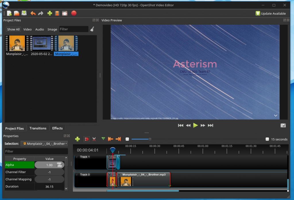
I also set up the beginnings of a slide deck on slides.com (https://slides.com/yuyis/cmu_capstone_asterism) to serve as an initial part of the demo video:
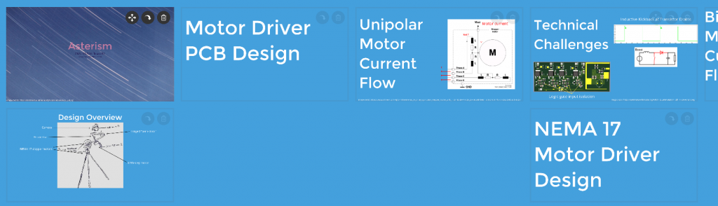
I intend for this slide deck to be used to introduce the general project topic/design, electrical systems, and computer vision component before seguing into a recording by Kenny using our actual project. Recordings of this slide deck using OBS-studio will be stitched together with voice recordings and background music using the OpenShot instance shown earlier.
Next week, I’ll be working on the final report, and working with Kenny to get the demonstration setup and recorded. I think that’ll be all for capstone this semester.
Final Presentation Slides
Team Status Update for April 25 2020
The biggest risk right now is an incompatibility between the physical circuit and the software implementation in the final day of product implementation before the presentation is due. A difficulty in this aspect could prove to be a costly delay. This has been mitigated mostly by a good amount of software level verification from both Joy and Yuyi.
No changes in schedule have been made so far as the dominating factor this week is the presentation.
Yuyi Shen’s Status Report for April 25, 2020
This week, I spent most of my time advising Kenny on the assembly and testing of the mount electronics. Soldering the surface mount components proved to be unexpectedly challenging, and we had to get around multimeter reliability issues, inadequate desoldering equipment, and solder-related issues (Kenny had inadvertently ordered lead-free solder paste for use with the SMD components, which meant that he had to deal with the intrinsic difficulties of using lead-free vs. leaded solder as explained here: http://www.pcboardrework.com/difference-between-lead-and-lead-free-solder/). In addition to advising him on his difficulties, I also laid out procedures that he could apply to ensure the functionality of the mount electronics, ranging from the usage of the laser diodes intended for the test setup as makeshift current indicators for the mount’s unipolar motor driver PCB to the application of an ammeter (in conjunction with a large 10W resistor) for safely testing the NEMA 17 motor drivers’ H-bridges.
Given that the majority of my contribution is complete, I’m reasonably on schedule.
Tomorrow, we will conduct experiments to characterize the tradeoffs inherent in our design. These include the following:
- The choice to use a custom PCB and circuit to implement the camera mount’s unipolar motor driver vs a typical UL2803 Darlington array. This tradeoff will mainly be evaluated by measuring the amount of current each device can supply to the mount’s unipolar stepper motor with a fixed supply voltage of 5V, and the temperature the transistors reach after 30 minutes of operation (as measured by infrared thermometer).
- The decision to use a custom H-bridge circuit for driving our NEMA 17 stepper motors (used to implement panning and tilting of the camera mount) vs. a commercially available motor driver (such as the Easy Driver). This will be tested by measuring the H-bridge MOSFET temperatures after 30 minutes of powering 1 or 2 motor phases, and comparing their average to the temperature measurements listed on this site: http://www.schmalzhaus.com/EasyDriver/#Q14. A simple figure of merit will be calculated from the current each driver is able to supply, and the operating temperature.
- We decided to implement our camera mount using a barn-door-style compensator to track the rotation of the starscape, instead of a more elaborate and accurate equatorial type mount. This style of mount usually experiences a form of tracking error called tangent error, which renders its usage impractical for exposures lasting longer than 5-10 minutes with a 50 mm lens. We intend to examine the degree to which our software-based compensation ameliorates this error by making progressively long exposures with a 56 mm lens with and without said compensation until star trails are visible on the image. The presence of star trails will be determined by comparing long exposures of the starscape with comparatively shorter ones, and measuring the relative sizes of the stars on the images.
Kenny Ramos Status Report 4.25.2020
This week was mostly spent on getting the last few particulars of physical assembly done. Tomorrow (Sunday 26 2020) will mostly be spent on getting data and video compiled for the upcoming presentation. As of Saturday 4/25/2020 at 9:16 pm the progress on each individual physical part is as follows:
- Small digikey bipolar motor driver/controller PCB (fully assembled, only needs to be plugged in [Rpi + motor + housed on physical mount]).
- Nema 17 unipolar motor driver and power supply (1 set [2 H-Bridges + 1 Power supply + heatsink] fully assembled] 2nd set is being debugged, I might attempt using replacement MOSFETs/BUCK converters to see if that gives better results)
- Wooden physical stand (each portion [1 ⅝’s wood door hinge assembly + polar scope + camera mounting slot] + [1 MDF declination axis mounting hinge] + [1 MDF turntable Right ascension mounting slot] individually assembled, once debugging is done it should be a matter of joining parts and wires)
On top of that a few visual aids have been set up for debugging and demonstration purposes:
- Arduino adc logger + matplotlib for plotting logged adc input over time.
- Simple led circuit for demonstrating test point connection to circuit ground for small digikey motor controller.
- As discussed previously a 10W-10Ohm resistor for measuring H-bridge current (currently being used for debugging)
Joy’s Status Update for 2020-04-25
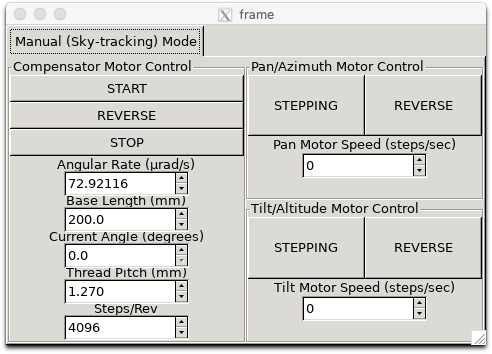
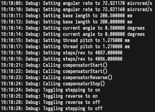
I was able to verify that CV code compiles on the Pi and works with the motor controllers and libgphoto2 camera input. I wrote a GUI app (attached is a screenshot) for the motor controllers and fixed some bugs that my teammates pointed out to me. I haven’t integrated the CV code into the GUI app yet, so I am behind on that. Next week we have our final presentation, and the week after that we have the final demo, so I will spend next week working on those with my teammates, working on integrating the CV code into the GUI, and working on any last-minute software improvements.
Team Status Update for April 18 2020
The principal risk to the completion of the project at this late stage is the slowness with which assembly of the mount is proceeding. We also need to finish addressing the integration of the CV routines Joy has written with the mount hardware, such as the libgphoto2 interface to the mount camera. Given the remote nature of most of the remaining work, the only recourse seems to be the scheduling of more frequent status meetings until the dates of the in-lab demo and the final presentation. We’ve also created a Google document to list goals for each day of this final week.
No changes to the schedule or system design have been made.
Here’s a picture of a partially assembled motor controller PCB:
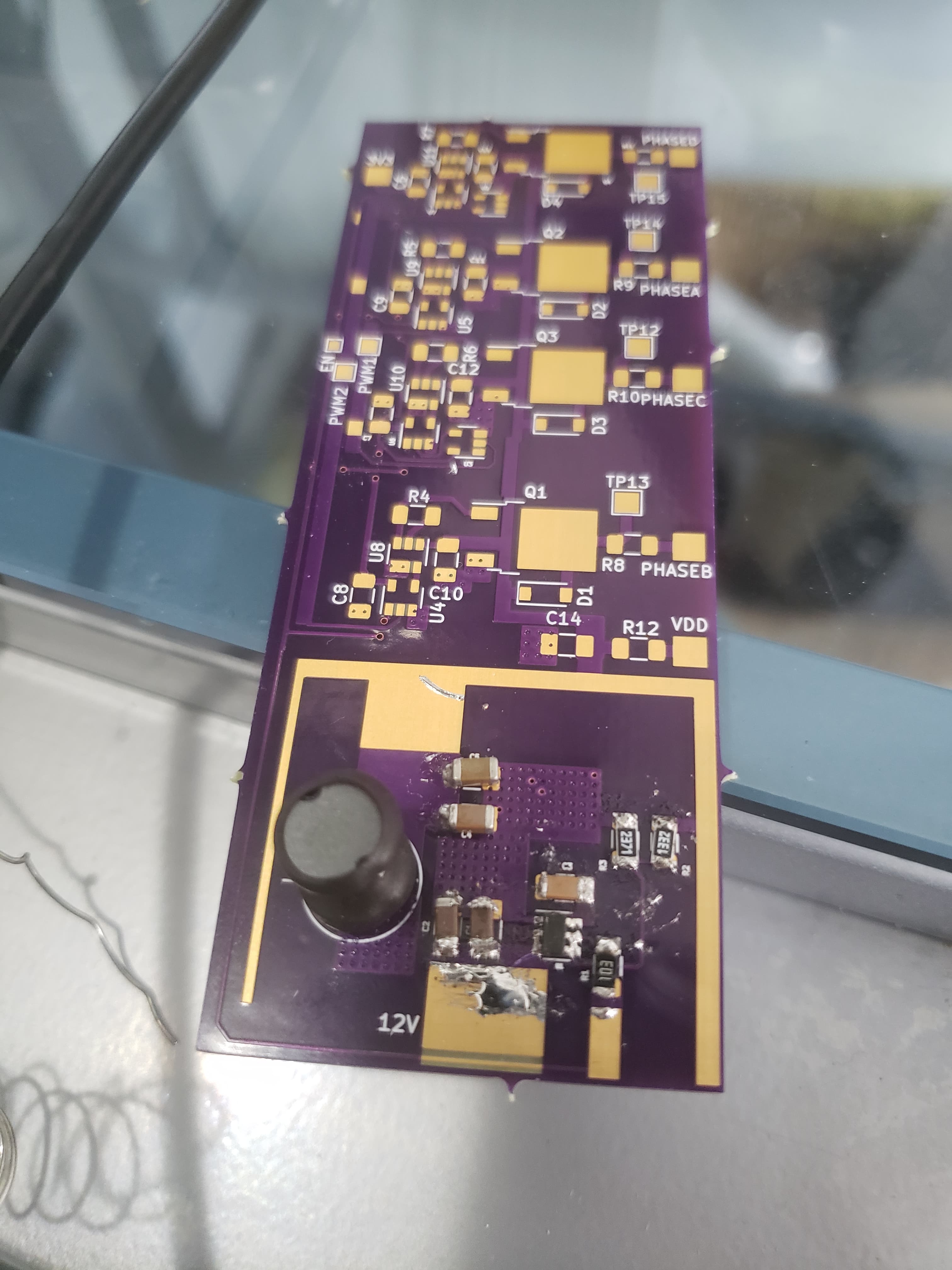
Feeding power to the 12V input of the buck converter that’s assembled on the bottom of the PCB causes the expected 5V to appear at the VDD pad, which is a promising result given the difficulty of soldering the SMD components. Tests of the remainder of the board (which composes the actual motor controller) should occur tomorrow afternoon at the latest.