April 20: Team Status Update

  • What are the most significant risks that could jeopardize the success of the project? How are these risks being managed? What contingency plans are ready?

-The lifting mechanism for the door is an open feedback loop. Careful testing is required.

-We are concerned about not having enough time to do testing on the full system.

  • Were any changes made to the existing design of the system (requirements, block diagram, system spec, etc)? Why was this change necessary, what costs does the change incur, and how will these costs be mitigated going forward?

The servo is changed to a DC motor because neither the servo nor stepper motor would cooperate. The DC motor will share the 12V power supply with the solenoid. The motor was given to us for free because it was a spare part for a Build18 team.

[Irene] DC Motor

I explored all the motor options in all their fullness of potential. Let me explain what was peculiar with each one:

NEMA17 & L298N (cheap from amazon):

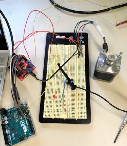
Using the stepper motor library, the motor stalls, as before, but setting the pins directly did not have the motor work. The same code that worked with the fake NEMA 17 and borrowed driver did not work for this motor and driver.

NEMA 17 & L298 hbridge (expensive from sparkfun):

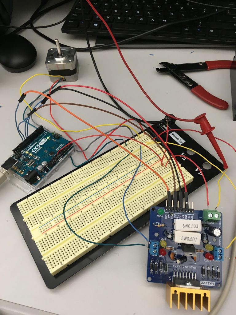
I could not figure out how to get this driver to work, despite trying various wiring configurations. The leds light up for MotorA and MotorB, which is a good sign. I tried hooking up the H-bridge and the motor to separate power supplies and the same power supply. I tried setting different combinations for the enA and enB pins, along with in0-in3 pins. I followed what the datasheet instructed for having a coasting motor. I researched what a stepper motor should be doing and found an article on stepping modes. I manually set the in0-in3 pins according to what the coils were expecting, and huzzah!

Animated GIF - Find & Share on GIPHY

I could not get the Full nor Half operation modes to work, but I got the Wave operation mode to work for counter clockwise rotation. Unfortunately, I could not get the stepper motor to rotate clockwise.

NEMA 17 & TB6600 motor driver:

Led indicator told me the motor was asking for more current, but it was asking for more than it was allowed to have according to the datasheet. I found various wiring instructions online, each slightly different. Nathan and I tried all sorts of configurations trying to guess how the motor should’ve been wired up, with little luck. Furthermore, peeling off the cover of the motor driver, I found that the labels on the pcb did not match the labels on the outside of the cover. The pulse pins were mislabeled as enable pins. I gave up on trying this option, but in hindsight, I bet if I fed the motor some more current, it might’ve behaved differently. On adafruit.com the NEMA 17 spec for max current says 350mA, but other sources say the motor can handle more. Weird.

Servos:

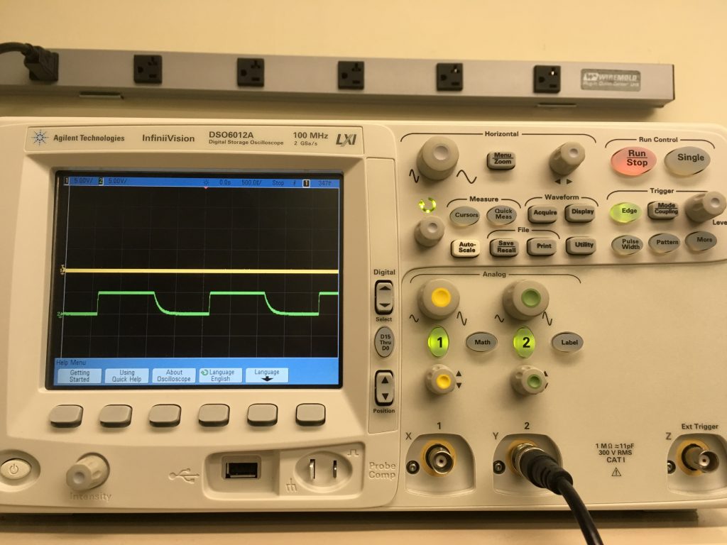
The PWM from my Arduino that worked so reliably last week no longer worked this week. The falling edge was not as fast as before, and my servos no longer cooperated with my Arduino.
Furthermore, I realized that PWM from Jetson is not a good idea. The easiest solution for PWM by far is to: connect to Arduino from Jetson TK1, so that your main program running on Jetson decides what the motors should do, and it sends that info to an Arduino that does the actual PWM control. To control motors or servo motors, you can either attach a servo motor shield onto a regular Arduino or use an Arduino clone that includes its own motor controller, so it didn’t need a separate motor controller shield. But if you use a regular Arduino then the easiest solution would be to add a servo motor shield to a regular Arduino. Low-level real-time operations like PWM need consistent “hard-realtime” timing that a microcontroller is much more suited to than a big CPU / Application Processor like Tegra.

DC Motor:

I had actually forgotten that I had a DC motor in my possession until Jing pointed it out. The motor asks for 12 volts, and has incredible holding torque when turned off – I didn’t measure exactly how much, but its more than even Professor Bain’s hands. Reversing the direction of current causes the motor to turn the other direction. I imagine I could probably form an open feedback loop circuit out of transistors to control the direction of the motor using gpio pins. Fortunately, I don’t have to. I can use the L298 hbridge (expensive from sparkfun). All I need to do is reverse the pin settings for in1 and in2 in order to reverse directions, and I can hold both pins at 0 in order to stop the motor.

void ccw() {
  digitalWrite(in1, HIGH);
  digitalWrite(in2, LOW);
}

void cw() {
  digitalWrite(in1, LOW);
  digitalWrite(in2, HIGH);
}

void hold() {
  digitalWrite(in1, LOW);
  digitalWrite(in2, LOW);
}

The jetson should be able to control the motor entirely through GPIO pins since only the enA, in1, and in2 pins on the H-bridge need to be set. And I can share the 12V power supply from the solenoid bolt. The motor draws at most .13A.

TLDR;

I have a motor that turns and I can control it.

I’ll mount the pully system tomorrow so we can show it off at the in class final demo. Next week, we’ll be doing the presentation. I will revise the project paper to according to design review feedback. I will have updated diagrams in the project paper according to system changes.

[Jing] Integration and Refinement

Since we ran out of AWS credits, I turned off the EC2 instance last week. However, this week we received more so I started a new EC2 instance. It turns out that when you start an AWS instance, it keeps the settings of the person who last used it. My AWS instance had a lot of problems because it wasn’t updated to the latest EC2 version, and had libraries which were different versions from the ones that I used, so my old code couldn’t run on the EC2. After reupdating the entire EC2, and uninstalling and reinstalling various versions of the libraries I was using, I was able to get my network to train, but I could not download the model. Instead I had to save the model as a checkpoint file, and then convert the checkpoint file to a saved_model object on my own computer.

I retrained the ML model with improvements to the convolutional neural network and the larger data set. I added several convolution layers and a batch normalization layer, as well as 600 more images (times 2 after flipping them). I ended up getting 84% accuracy on the validation set.

I also helped Philip get libraries set up on the Jetson and we were able to successfully run our computer vision + machine learning code on it.

Unfortunately, I fell sick during the latter half of this week.

April 13: Team Status Update

  • What are the most significant risks that could jeopardize the success of the project? How are these risks being managed? What contingency plans are ready?

We are worried about not having enough time to do testing on the full system. We have already cut away at unnecessary improvements such as optimizing the ML algorithm for the Jetson.

  • Were any changes made to the existing design of the system (requirements, block diagram, system spec, etc)? Why was this change necessary, what costs does the change incur, and how will these costs be mitigated going forward?

No changes.

  • Provide an updated schedule if changes have occurred.

[Philip] Jetson working with Tensorflow

I was originally hoping that Jing’s ML algorithm and Irene’s CV algorithm would smoothly work on the Jetson. I had prepared for this by installing all the necessary libraries for Tensforflow and OpenCV, in addition to the TensorRT libraries. However, after attempting to run the Python script on the Jetson there was a library mismatch. The drivers for the GPUs were too old of a version to work with the Python script. Unfortunately, there is no easy way to update the drivers. Originally, I was using the OS that boot up out of the box. Now, I had to download the most recent OS and re-flash the whole board.

After the re-flashing of the board, I had to reinstall all of the libraries. This process was a lot quicker than previously because I already knew what I had to do, but was rather tedious. Finally, Jing and I started to try and run the Python script. The Python script ran perfectly well on his PC laptop, now we just had to get it to run on the Jetson. After updating to the newest version of Tensorflow, and modifying bits and pieces of the CV and ML portions of the code, we were finally able to get it to work! It ran very fast, although this conclusion is just from my eye’s view, we have yet to run tests.

My progress is behind due to the complications that arose in running the Python script on the Jetson. To catch up, I will not be focusing my time on optimizing the algorithm for the Jetson, as this is not a necessary aspect of the project, simply a desired aspect.

In the next week I will be working on fully integrating the entire system. After this is accomplished I hope to be running a variety of tests on the system.

[Irene] Motor Drivers

I used a waveform generator to output a square wave with T = 2.0ms, Ampl = 3.3Vpp, HiLevel = 3.3Vpp, Offset=1.65Vdc, LoLevel=0V, and Duty Cycle between 20% and 80%. The servo seems to work fine, with a few glitches when the duty cycle was low.

Animated GIF - Find & Share on GIPHY

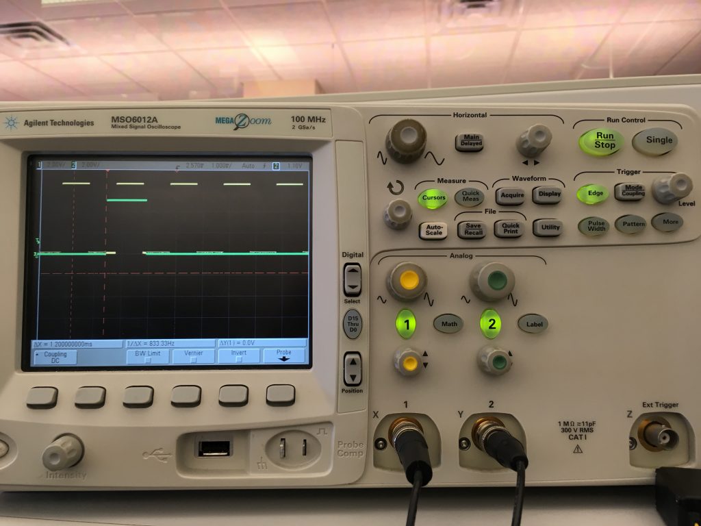
However, using the servo library on the Arduino, the pwm output from pin 9 looks funny. Here is a comparison on the oscilloscope:

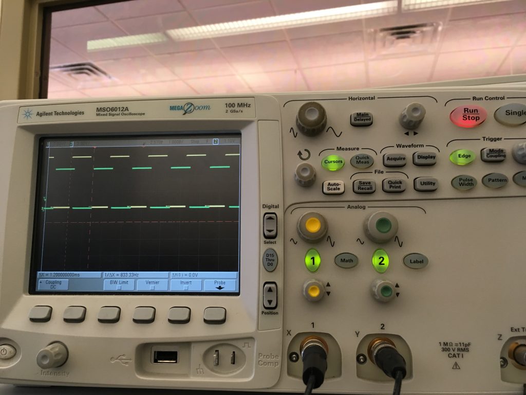
Yellow is the square wave from the waveform generator, and green is the output from the Arduino using the servo.h library and the sample code provided by adafruit here https://learn.adafruit.com/adafruit-arduino-lesson-14-servo-motors/arduino-code-for-sweep. Upon inspection of the Arduino servo library, it looks like the servo.write() function sets an interrupt. When I set my own pwm using the following code:

void loop()
{
  digitalWrite(servoPin,HIGH);
  delayMicroseconds(active_us);
  digitalWrite(servoPin,LOW);
  delayMicroseconds(period_us - active_us);
}

Hallelujah, the Arduino output has the correct duty cycle and period, but the amplitude voltage is lower. Here is what the output from the oscilloscope looked like:

In the context of the system, I would need to use interrupts to manage the PWM when integrated with the sensors.

I ordered parts for five alternatives because I don’t think we have time for ordering parts for a Plan B. In order of potential, my options are:

  1. NEMA 17 & L298 hbridge (cheap from amazon): There are many resources out there using these two parts together and I (almost) had it working with the same type of hbridge last week. 
  2. NEMA 17 & L298 hbridge (expensive from sparkfun): I’ve learned from Build18 that cheap parts are not reliable, so here’s an alternative. The hbridge is the same model, but the breakout board looks more enhanced. The heat sink is larger.
  3. NEMA 17 & TB6600 motor driver (as recommended by Nathan Serafin). This driver is very heavy duty and reliable, but there are not many resources out there for how to use it.
  4. Continuous rotation servo: I feed this a time interval and it spins for that amount of time, but is very imprecise.
  5. The original servo: I believe I could hack something together to make this work, but it wouldn’t be pretty. I have better options, and this is only a backup on backups.

If the option that I go with does not have enough torque (which is unlikely), I can use a counterweight to require less torque.

I got through trying options 1-3. Here are my results.

  1. NEMA 17 & L298 hbridge (cheap from amazon):Animated GIF - Find & Share on GIPHY

    The motor stutters, but is drawing much less current than the imposter NEMA 17.

  2. NEMA 17 & L298 hbridge (expensive from sparkfun): I wired everything, but there is no current flowing. I looked at the user manual and found operating instructions that include the use of ENA and ENB, which I haven’t needed to use before when following other tutorials. I will try more wiring configurations
  3. NEMA 17 & TB6600 motor driver: This I have no clue how to wire up (LOL). I will meet with Nathan to figure it out.

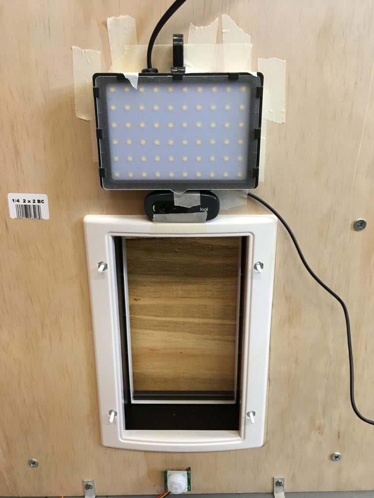
In other news, I have mounted the camera and LED to the door. They are both taped on so we can remove or adjust them.

Here is what the camera output looks like:

And with the lights off and LED on:

And I was standing about two feet away:

I’m behind and still working to solve the same problems as last time.

[Philip] OpenCV and GPIO

OpenCV is the standard for computer vision. However, it was not made to be put on an Nvidia Jetson board. Nvidia is trying to fix this, and have created an easy-to-use SDK installer. However, this installer is in beta. It was very easy to pick and choose which libraries to install on my board until the SDK would not properly connect to the board. Unfortunately, I had to revert to a much more complicated way which I figured out by compiling multiple advice pages on the internet. In the end, I got OpenCV working by getting a simple python script to display the video feed coming from a USB camera plugged into the Jetson.

Originally, I planned on continuing to work on the app. However, I realized that my work with the GPIO pins that I had previously done was useless because it was written in C++. Previously, I used a GPIO library I found for the Jetson TX1 which I edited for the TX2. However, I was not able to find a GPIO library in Python. Therefore, I had to write the GPIO library from scratch including functions such as Export, Unexport, setDirection, SetValue, GetValue, and ActiveLow.

My progress is slightly behind because of having to write the GPIO library in Python.

My goal for this week is to get Jing’s graph integrated with TensorRT. After some preliminary research, this does not seem straightforward as I had hoped.

[Jing] More AWS credits, and Solenoid

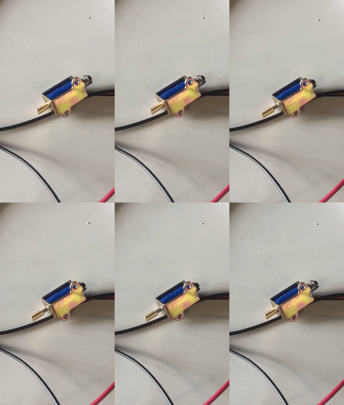
This week I tested the solenoid and ordered a 12V DC Adapter and breadboard to help power the solenoid. I built the same circuit as the solenoid circuit diagram I drew last time.

I also scraped a few hundred more images off of Google to increase the size of our data set for Machine Learning (300 more images of raccoons, and 200 more images of lower body, which took like 3 hours to get). I’ll continue to find more images so that we can have at least 600 or 700 of each. I am also considering taking out the “squirrel” prediction, because the chance that we see squirrels is low and isn’t imperative towards our primary goal, which is to differentiate between cats and raccoons and humans.

Unfortunately, the $100 of AWS credits we had ran out, so I requested more AWS credits (and hopefully will receive them). We initially requested $150 of AWS credits several weeks ago, but one of the codes didn’t work so we only had $100 to work with. I won’t train anymore on the EC2 for now until we get more credits to work with. However, as soon we as have more AWS credits (or in the case that we don’t get any, we’ll use our budget), 

Finally, I tested the Computer Vision + ML inference on the cat that we had at home, as well as on my own self. I’ve recognized a few patterns in the algorithm. If there are any long, leg-like objects of a solid color in the image, it will recognize that as the lower body of a human (for the most part). If there are any gray animals or if there is too much gray color in the image, it detects that as a raccoon, since the raccoon images I have are mostly gray. As of now, the predictions mostly depend on colors in the image, as I stated above. Additionally, the ML inference will return classification probabilities with 97%+ accuracy. In other words, the inference gives us extreme results, whereas having uncertain results (such as a classification probability of 60%) is actually more helpful. After researching online, having a larger data set will help alleviate this (as a larger data set will help alleviate most problems), as well as implementing k-fold (usually 10-fold) cross validation. What cross validation is, is shuffling the data set and retraining on it using random partitions of the data set as the training set and validation set. This is what I plan on doing by the next time I train (which should be by Wednesday April 10).

Next week I will focus on implementing k-fold cross validation, finding more images, and getting the CV and ML code to run using TensorRT.

[Irene] Motor Alternatives & Timing

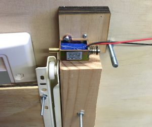
First, I attached the solenoid to the door:

I happened to be in the right place at the right time to overhear Professor Nace say that Ryan Bates from Tech Spark has a box of stepper motors. I talked to Ryan and he let me borrow a stepper motor and L298N Dual H-Bridge Motor Controller. When I followed a tutorial using the same motor and H-bridge motor controller with an Arduino, I couldn’t get the system working.


I poked around with an oscilloscope and saw that there is current flowing through the H-bridge, but not a lot. Next, I asked Nathan Serafin for advice, and he said he could lend me a few motors. I tried switching out the motor, but the motor still did not work. I met with Sam to try to get the motor working, and he pointed out that my power supply could not source the amount of current needed at the voltage wanted. He borrowed a bigger power supply from the CMR garage, and the motor didn’t work, so we tried borrowing an identical H-bridge component from another team. The motor moved with the new H-bridge, but the H-bridge was overheating. So we concluded that the H-bridge from Tech Spark was faulty, but that particular H-bridge model is not strong enough to support the stepper motor. Sam suggested I investigate the servo again, which I will be doing. I also talked to Nathan Serafin again and he suggested researching this alternative H-bridge.

In between all the motor things, I found time to do a timing analysis on the integrated machine vision script. I segmented the code into the following blocks: initialization, resizing, converting to grayscale, applying Gaussian blur, calculating frame delta & applying binary threshold & computing contours, tracking where to crop, prediction, and drawing the frame. I counted the number of times each block was executed, the total time spent executing a code block, and the total time for execution of the whole script. I found that image saving, image resizing and drawing things on top of the frame took the most time. Therefore, for the integrated script, I removed the text and rectangle overlays on top of the frames and only displayed one frame. I am keeping the motion detection script separate with all the intermediate frames displaying for the purposes of fine tuning and debugging.

I will be placing orders for alternative motor parts and trying them out. In the next status report, I will detail the pros and cons of each alternative, and why they did or did not work. I’m busy until the start of carnival, which works out well because the new parts will not arrive until Thursday at the earliest. I can work over Friday and Saturday.

April 6: Team Status Update

Risks -> Contingency Plans
  • Not getting a stable motor component -> research other H-bridge components and find out why the servo isn’t working
  • Low accuracy -> add a null prediction value to the algorithm
Changes to system design -> why changes are necessary
  • Stay tuned for next week’s update when we find out what motor we’ll be using
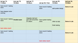
Updated schedule