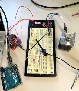
I explored all the motor options in all their fullness of potential. Let me explain what was peculiar with each one:
NEMA17 & L298N (cheap from amazon):
Using the stepper motor library, the motor stalls, as before, but setting the pins directly did not have the motor work. The same code that worked with the fake NEMA 17 and borrowed driver did not work for this motor and driver.
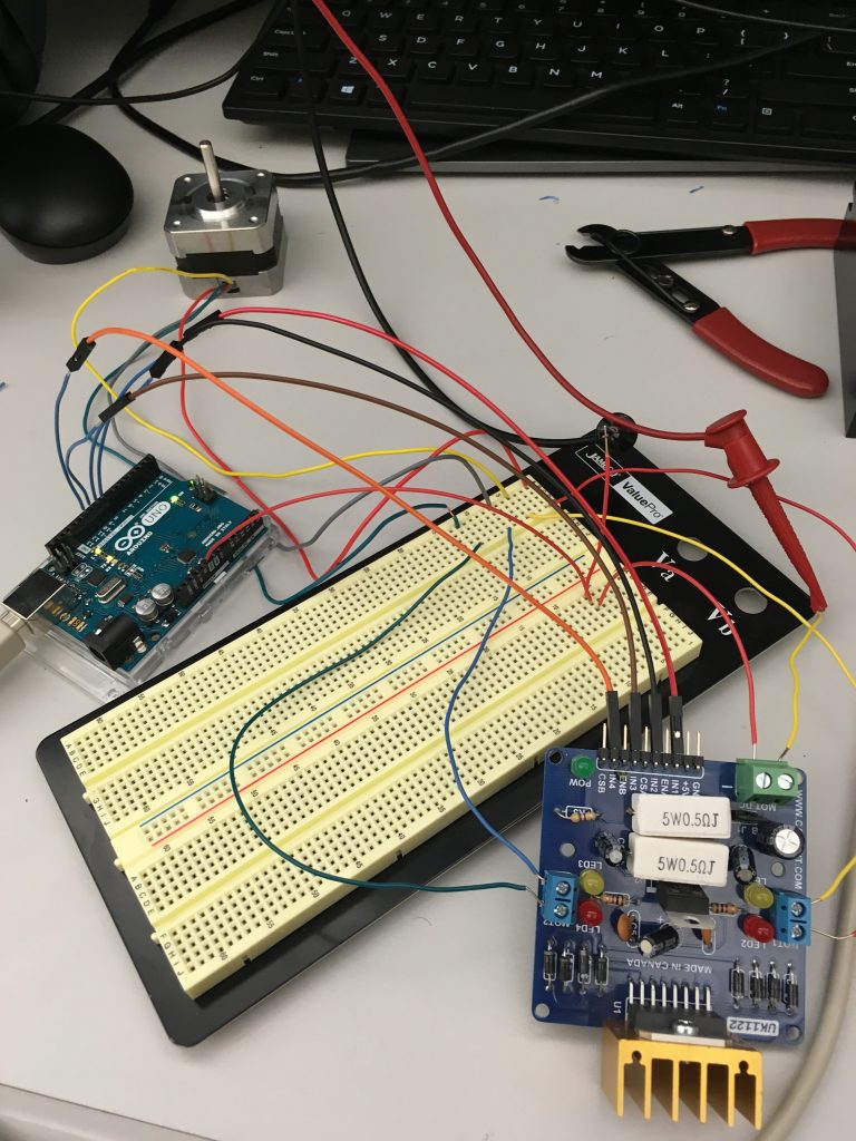
NEMA 17 & L298 hbridge (expensive from sparkfun):
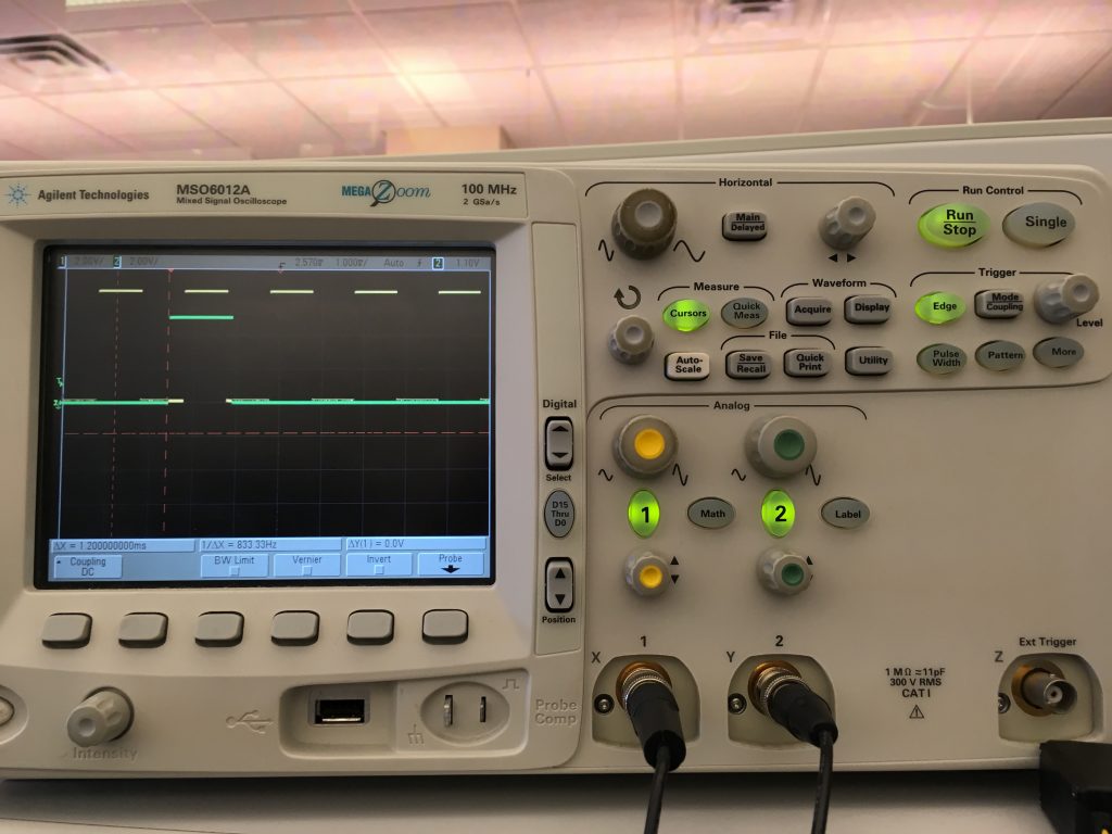
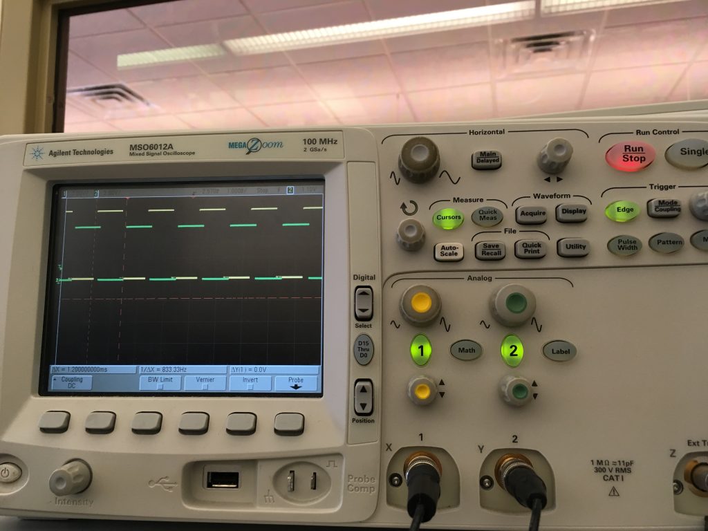
I could not figure out how to get this driver to work, despite trying various wiring configurations. The leds light up for MotorA and MotorB, which is a good sign. I tried hooking up the H-bridge and the motor to separate power supplies and the same power supply. I tried setting different combinations for the enA and enB pins, along with in0-in3 pins. I followed what the datasheet instructed for having a coasting motor. I researched what a stepper motor should be doing and found an article on stepping modes. I manually set the in0-in3 pins according to what the coils were expecting, and huzzah!
I could not get the Full nor Half operation modes to work, but I got the Wave operation mode to work for counter clockwise rotation. Unfortunately, I could not get the stepper motor to rotate clockwise.
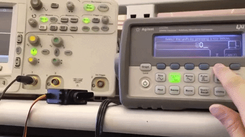
NEMA 17 & TB6600 motor driver:
Led indicator told me the motor was asking for more current, but it was asking for more than it was allowed to have according to the datasheet. I found various wiring instructions online, each slightly different. Nathan and I tried all sorts of configurations trying to guess how the motor should’ve been wired up, with little luck. Furthermore, peeling off the cover of the motor driver, I found that the labels on the pcb did not match the labels on the outside of the cover. The pulse pins were mislabeled as enable pins. I gave up on trying this option, but in hindsight, I bet if I fed the motor some more current, it might’ve behaved differently. On adafruit.com the NEMA 17 spec for max current says 350mA, but other sources say the motor can handle more. Weird.
Servos:
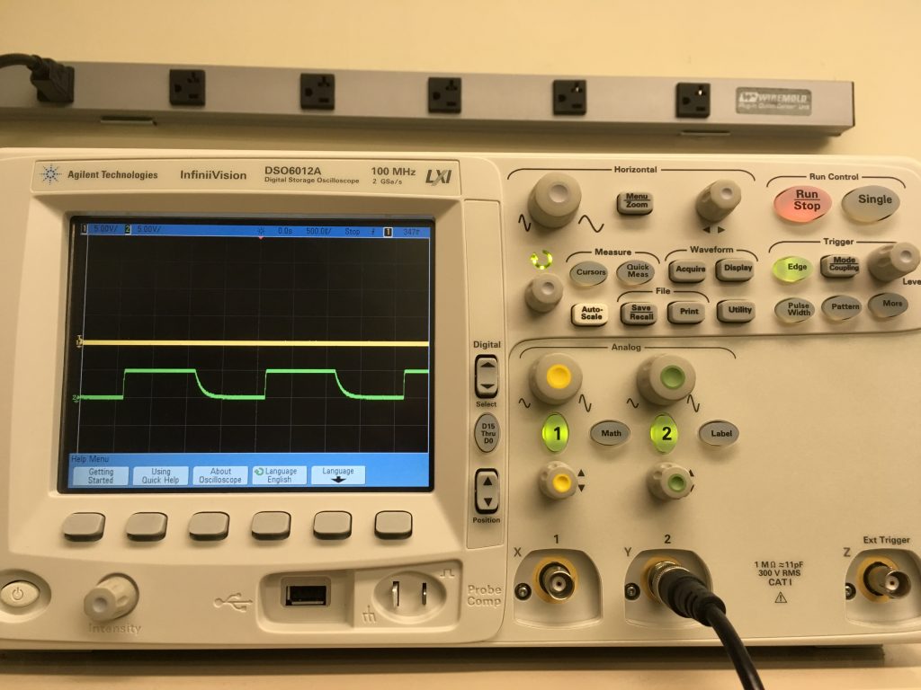
The PWM from my Arduino that worked so reliably last week no longer worked this week. The falling edge was not as fast as before, and my servos no longer cooperated with my Arduino.
Furthermore, I realized that PWM from Jetson is not a good idea. The easiest solution for PWM by far is to: connect to Arduino from Jetson TK1, so that your main program running on Jetson decides what the motors should do, and it sends that info to an Arduino that does the actual PWM control. To control motors or servo motors, you can either attach a servo motor shield onto a regular Arduino or use an Arduino clone that includes its own motor controller, so it didn’t need a separate motor controller shield. But if you use a regular Arduino then the easiest solution would be to add a servo motor shield to a regular Arduino. Low-level real-time operations like PWM need consistent “hard-realtime” timing that a microcontroller is much more suited to than a big CPU / Application Processor like Tegra.
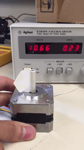
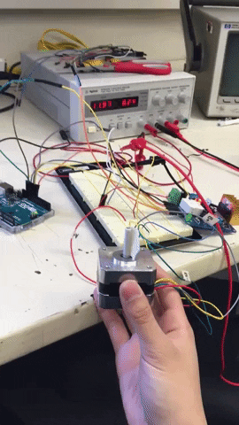
DC Motor:
I had actually forgotten that I had a DC motor in my possession until Jing pointed it out. The motor asks for 12 volts, and has incredible holding torque when turned off – I didn’t measure exactly how much, but its more than even Professor Bain’s hands. Reversing the direction of current causes the motor to turn the other direction. I imagine I could probably form an open feedback loop circuit out of transistors to control the direction of the motor using gpio pins. Fortunately, I don’t have to. I can use the L298 hbridge (expensive from sparkfun). All I need to do is reverse the pin settings for in1 and in2 in order to reverse directions, and I can hold both pins at 0 in order to stop the motor.
void ccw() {
  digitalWrite(in1, HIGH);
  digitalWrite(in2, LOW);
}

void cw() {
  digitalWrite(in1, LOW);
  digitalWrite(in2, HIGH);
}

void hold() {
  digitalWrite(in1, LOW);
  digitalWrite(in2, LOW);
}
The jetson should be able to control the motor entirely through GPIO pins since only the enA, in1, and in2 pins on the H-bridge need to be set. And I can share the 12V power supply from the solenoid bolt. The motor draws at most .13A.
TLDR;
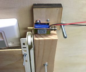
I have a motor that turns and I can control it.
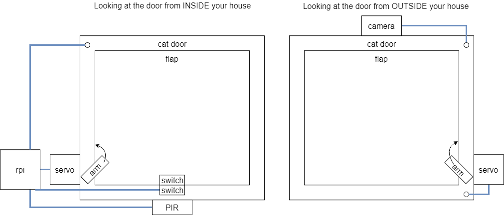
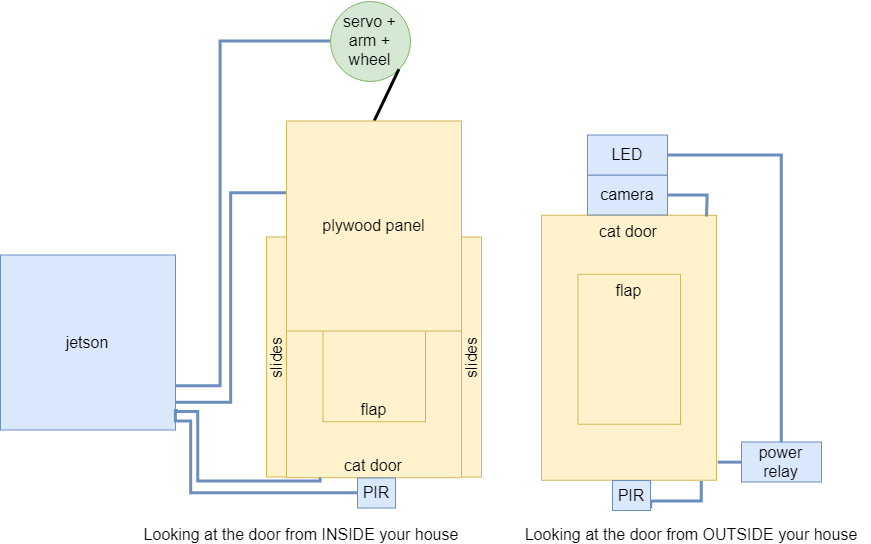
I’ll mount the pully system tomorrow so we can show it off at the in class final demo. Next week, we’ll be doing the presentation. I will revise the project paper to according to design review feedback. I will have updated diagrams in the project paper according to system changes.