Progress
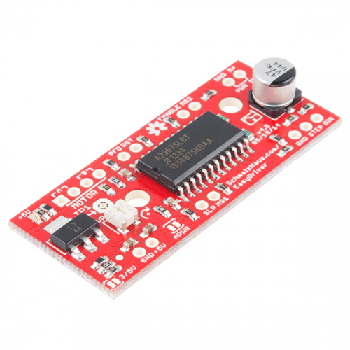
In week 9, we tested web communication portion and was able to send a command from the web app to control the IR circuit. I had some progress with development in the motion and dynamics portion of the project. Firstly, I have started soldering the motor driver according to the schematics that I made. And I have managed to migrate all the code in Arduino sketch to python to be run on an RPi.


Some Important inputs for controlling the stepper motor are specified below:
- MS1 – Logic Input for the stepper step size. See truth table below.
- MS2 – Logic Input for the stepper step size. See truth table below.
- STEP -Logic Input. Any transition on this pin from
LOWtoHIGHwill trigger the motor to step forward one step. Direction and size of step are controlled by DIR and MSx pin settings. This will either be 0-5V or 0-3.3V, based on the logic selection. - DIR -Logic Input. This pin determines the direction of motor rotation. Changes in the state from
HIGHtoLOWorLOWtoHIGHonly take effect on the next rising edge of the STEP command. This will either be 0-5V or 0-3.3V, based on the logic selection. - ENABLE -Logic Input. Enables the FET functionality within the motor driver. If set to
HIGH, the FETs will be disabled, and the IC will not drive the motor. If set toLOW, all FETs will be enabled, allowing motor control.
Microstep Select Resolution Truth Table
| MS1 | MS2 | Microstep Resolution |
|---|---|---|
| L | L | Full Step (2 Phase) |
| H | L | Half Step |
| L | H | Quarter Step |
| H | H | Eighth Step |
The stepper motor works surprisingly well with no additional tuning needed. In the motor control loop, I found that when i=1600 on Eighth Step Mode, the stepper will exactly do one revolution and i=200 on Full Step, the stepper will exactly spin for one revolution.
Last week, we tested the range of IR diodes and its field of view. We found the FOV of a single IR diode is about +- 5 degrees and because of the narrow FOV, when the targeted object is far away from the diode, a little bit of deviation for the angle would greatly amplify the error, hence failing to pinpoint the IR signal at the target device. Therefore, we decided to have a few more IR diodes in parallel so that we can cover a greater FOV and bigger tolerance for the motion of the motors. Thus we decided to put them into bundle like this. We will do some performance tests on these later on in this week.

On this weekend’s development, we continue on writing the multi-threading portion of the client-side code to have RPi control IR circuits and motors simultaneously and finish all the motion related code.
Schedule
This week’s development is on schedule. Now shifting more focus to integrating web communication part and the motor control with the hardware.
Deliverables Next Week
- Start making the IR Man figurine and all the necessary 3D printed parts.
- Start writing the multi-threading client code to test the web communication feature on the RPi.
- Pull the IR commands from the LIRC database and write that into the lirc.conf file for all the devices we want.
- Finish all the motion code for the motor and think about the operating scenarios.
- Start Soldering the IR Circuits onto PCB board.
- Help Shirely to collect and label pictures of our target devices.
0 Comments