Sarah’s Status Report for Saturday, Mar. 28

This week, I mainly worked on writing up time delay beamforming processing.

For a linear array of microphones that are located perpendicular to the sound source, the signals captured by the microphones have similar wave forms but varying delays. In order to account for these delays, I calculated it from speed of sound, distance between the microphones and the sound sources. Also, signals must be shifted for runtime difference. Finally, all the signals can be summed up. The summed signal is then normalized by the number of microphone channels.

For next week, I plan to run simulations with sample data and fix any problems that come up.

Jonathan’s Status Report for Saturday, Mar. 21

All of the changes to daily life this week didn’t leave much time for work on capstone outside of class, so the additional work completed has been minimal.

Most of what I was able to work on this week was design of the microphone array boards, which was originally scheduled to be finished over the last couple days of Spring Break.

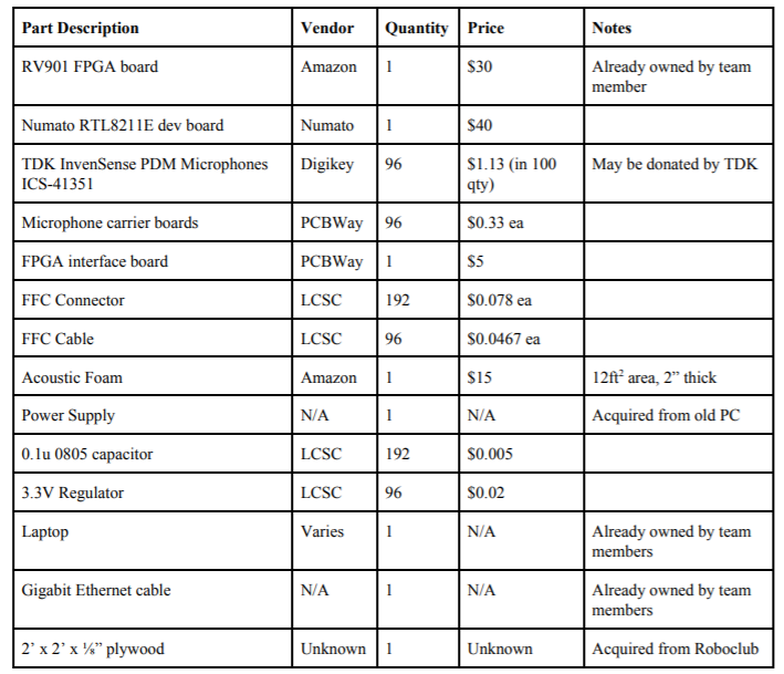
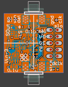
I was able to complete a simple breakout for the microphones, as we’d originally planned to have an array where each element is identical, and on its own small carrier board, with the boards connected to the FPGA with FFC cables.

However, with the changes to the project, I decided this was probably too work intensive to build for a single person to complete, and, difficult to build without the tools we expected to have available.

Instead, the design was changed to a set of 6 boards, each with 16 elements, and a single connector to the FPGA.  This board is still in progress.

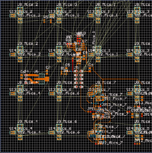
This cuts down the total number of components needed significantly, and reduces the number of connectors from about 200 to just six.  The drawback is configurability, if we later find that the 1″x1″ array spacing does not work well, there is not much path to changing it, some workaround would have to be found.  All of the analysis so far has indicated that 1×1 is close to optimal for the frequencies we’ve chosen, but, practical testing will undoubtedly find problems that simulation did not account for.

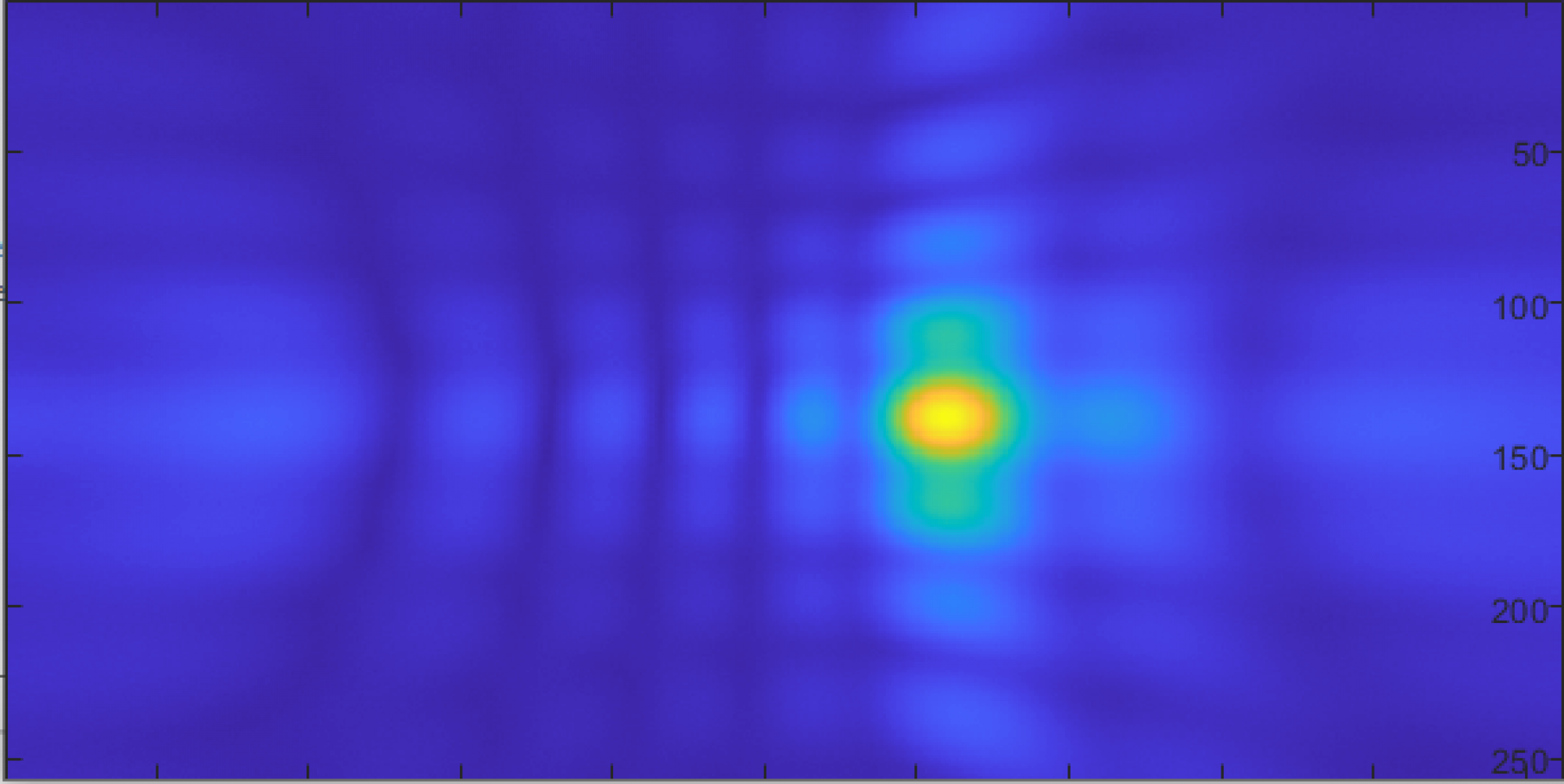
I have done some analysis of possible workarounds to changing array geometry, mostly pertaining to moving the sub-arrays slightly off-grid relative to each other (so, for example, two array are placed with their nearest elements just 0.5″ apart instead of 1″), which does allow for aliasing and other artifacts to be traded off with directivity, though the tradeoff is often steep in whatever is being traded against (i.e. to gain a little directivity, you have to tolerate significant artifacts, and vis versa).  Hopefully we will not have to do any of this, and all the analysis so far says we won’t, but it is good to know roughly what we’re facing if we do have to.

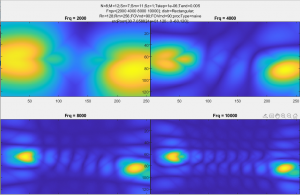
Photo shows some of the strange artifacts that emerge with unevenly spacing sub-arrays.  The two sources are real sources, so the array is not aliasing, but the sources are no longer round, they are shaped strangely, and, not exactly the same.  The output is still usable, but this illustrates a significant tradeoff of this method of constructing the array.

Team Status Update for Saturday, Mar. 21

This week brought some significant changes to the project, the new scope is summarized in our updated SOW:

Team E0 Statement of Work_3_21_20

Short summary is that the only major changes are to the details of the design, to account for losing access to campus resources, and several tests/characterizations/calibrations of the array will no longer be possible, and will therefore not be performed.

Work will be roughly divided by area, John will construct the physical array, Ryan will write the software to do audio-level processing, and Sarah will write the software to do array-level processing.

With the shutdown of roboclub and most other campus resources, we’ve had to check out most of the tools that we planned to use to construct the project, and set them up an at-home lab.  That along with the mass of changes to all of our daily lives this week has taken up most of our time, so not much more has been completed.

A few things have been done though, some amount of board design for the microphone carriers was done (see John’s update for details), though still in progress, and, the reel of microphones arrived from TDK/InvenSense.

Sarah’s Status Update for Saturday, Mar. 21

This week, I had a meeting with my team members and Professor Sullivan to talk about modifications in our project. Since my team will have to work on the project remotely for the rest of the semester, we have to break up the parts so that the workload is evenly divided to each person. We are thinking to have Ryan collect audio date from the microphone array and pass it to John for processing and then finally passed to me for localization. There need to be more discussions on the plan for the upcoming week. In addition, I worked on coding PDM to PCM in Python. I also researched about localization of audio sources in Python as well.

Our schedule will need to be modified due to the remote working environment. Yet, I am still on track with the major components.

Next week, I will have more discussions with my team members and work on debugging python code.


Ryan’s Status Report for Saturday, Mar. 21

After talking to Patrick from TDK Invense, we were able go get 110 of the ICS-41351 from them. We’re very thankful for this because this would have been the most expensive part of the project, as shown below in the bill of materials from the design report:

If we were to order the microphones from Mouser, it would have costed $124.30. Now, we’re able to allocate that for monetary slack, as we may encounter situations during the build process that we may need to order new parts.


The candidates for the microphones were ICS-41351, INMP521, and INMP522. The latter two had slight better frequency response at the frequency of interest (5kHz and above), but we ultimately decided on the ICS-41351 because it had a footprint that was much nicer to work with.

It has relatively large pads on the bottom:

Because it has the microphone port on the top, the bottom solder pads are not constrained.

The INMP521 and the INMP522 however, have the microphone ports on the bottom, so it becomes  much more challenging to solder properly, because the solder ring around the port has to be completely soldered for best acoustic performance, and it’s not easy to verify proper soldering when we do not have access to professional reflow tools.

The main task moving forward is to get the PCBs that John designed made and reflow them. I think it’ll be a fun challenge.

Sarah’s Status Update for Saturday, Mar. 14

Before heading off for Spring break, there were some updates.

I worked on finalizing PDM to PCM code with help from Ryan. The FIR low pass filter I used has a large order which has a narrow transition band. The image below shows our filter.

The image below shows the filtered PDM signal using the FIR filter.

It shows that there is high-frequency content, critical for identifying our sound source. I plan to test more pdm data for similar results.

I also worked on the design report with my members. We received feedback from Professor Sullivan and will further discuss the details through our meeting.

We are on track and there are a few things to do this coming week as planned.

To do next:

  • Discuss with my team members about re-scoping the project and make design decisions due to a change in our locations.
  • Discuss design report feedback with members.
  • Work on pdm to pcm in Python.


Jonathan’s Status Report for Saturday, Mar. 14

Unsurprisingly there were some significant changes to the progression of the project this week.  Before the switch to online classes was announced, I completed two things for this project, pertaining to the aspect which was slightly behind schedule, the gigabit ethernet.

The Numato PHY was ordered last week, but had not come in by Wednesday, so I decided to freehand solder the ADIN1300 sample that we already had.

The ultimate purpose of this was to debug the RGMII implementation, which should be a lot easier, since we have a full datasheet for the ADIN1300.  To this end, I added a microcontroller to communicate with it over the MDIO interface.

By looking at the errors that came up when attempting to use it, I eventually found that some of the bits were backward (forward for RGMII, but ethernet is lsb first, so the preamble and CRC were backward, though the payload was correct).  Also the CRC computation was slightly off.  Both of these issues were fairly easy to fix, and the end result was that I was able to send UDP packets to my computer.

Applying these changes to the other board (the RV901), got it working as well.  Given the interruption to everything from Corona and that this is working as is, we’ll probably end up using this board for the final device to save time.

The day after I got this working was when all the Corona stuff really started kicking off, so I haven’t gotten much further than this.  I did start on the microphone carrier boards, but the design of that may have to change to deal with suppliers (possibly) not being open.

Ryan’s Status Report for Saturday, Mar. 14

This week, we’ve worked on creating the FIR filter for converting the 1-bit 1-3MHz Pulse Density Modulation output of the microphone to a standard double precision array in MATLAB. Essentially, the FIR filter is a lowpass filter that only allows signals below 20kHz (human hearing range) to pass through.

We used MATLAB’s Filter Designer tool to generate a lowpass FIR filter with 1.000MHz sampling frequency, 20kHz passband, 25kHz stopband. The resulting FIR filter had 506 taps. I could have lowered the stop band at the expense of higher filter order, but I didn’t want to slow the system down too much during the actual filtering process. We will see if a sharper filter is needed. The FIR filter has the following frequency and phase response:

In order to apply the filter, we perform a convolution of the signal with the coefficients of the filter.

Original PDM signal, zoomed in:

Filtered result:

Filtered result, zoomed in:

Great, we are getting our 850Hz tone that we applied to the mic back!

Further considerations:

  • The process of convolving the PDM signal with the FIR filter seems to take a few seconds in MATLAB. We will need to optimize this for a realistic processing time for all 96 microphones.
  • I was not able to get the resulting signal’s audio to play in MATLAB. I do hear some pops and crackles though, so there must be a way to play a double array.
  • In talks with Patrick from TDK Invensense for microphones. We may be able to source the microphones from them instead of Mouser or Digikey, saving us a lot of money.


Jonathan’s Status Update for Saturday, Feb. 29

This week I mainly worked on the design report, and debugging ethernet.

After CDR we had a few comments, one of which was concerning the choice of FPGA.  Based on that, I went through and evaluated whether we should switch up to a newer/larger FPGA.  I did some preliminary checks on the expected size of the final design, as was suggested during CDR.  Since there is very little processing done on the FPGA, it is mostly just used for data acquisition, the required logic took around 30% of the space available, even with an intentionally inefficient PDM filter.

This used some stand-in logic for the microphone acquisition and filtering, but should take similar space to the final filter.

I also worked some with Ryan on the PDM microphones, we were able to get some very basic data off of a microphone (in this case, given an 820Hz sine wave):

One minor change to the plan is that we plan to buy the Numato PHY this coming week, as the GbE development is falling behind.  Other than that, we are still on track.  In the mean time, I will also begin using a simple USB 2.0 interface for the FPGA based on a teensy 4.0, as a stop-gap while working on GbE.

Sarah’s Status Update for Saturday, 29 2019

This week, I presented the Design Review Presentation. We focused on specifying the metrics and validation of our project.  Many helpful feedbacks were given by the audience. After receiving peer review feedback, I personally learned how I presented in front of people. I realized that I lacked skills in speaking loudly and having eye contact with the audience. The feedback also included some specific comments about our design as well. We are looking forward to covering the feedbacks on including array geometry and simple frequency analysis for our design report. The comments were very helpful.

(output of analog to pdm with simple signal)

In addition, I created analog to pdm converter as shown above. The code can used for testing purposes. Furthermore, a basic pdm to pcm is coded with the help from Ryan. He found a nice library in MATLAB that had the necessary functions to do so. The plot can be seen in Ryan’s Saturday Report. Yet, we do have considerations that the current code is not efficient enough for 96 microphone array. Some more filtering should be done.

A potential solution is found to be using a CIC filter. CIC filters achieve both decimation and interpolation without using multipliers.  We find this a good alternative to the current design of pdm to pcm.

In terms of the schedule, we are on track.

For next week, I look forward to starting coding in Python or Java since we are currently working on MATLAB codes and look for efficient manners of computing the pdm to pcm.