Team Status Update for Saturday, Feb. 29

We’re continuing our investigation with implementing 1Gbps Ethernet with our FPGA. The Spartan 6 board does come with two Gigabit Ethernet ports, but since it’s not a development board (actually an LED array controller), the Broadcom transceiver does not have a public datasheet for it, so it’s hard to control, even though it’s using the industry-standard RGMII protocol.

Instead, we’re looking into an expansion board with the Realtek RTL8211E from Numato. It has very good documentation that should make implementation much easier:


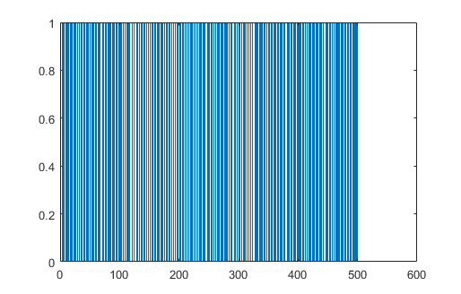
The output of the PDM microphone is a 1-bit digital signal. Even if the output is 1-bit high quality audio can be transmitted due to the fact that oversampling is occurring. For example, refer to this diagram below (Wikipedia):

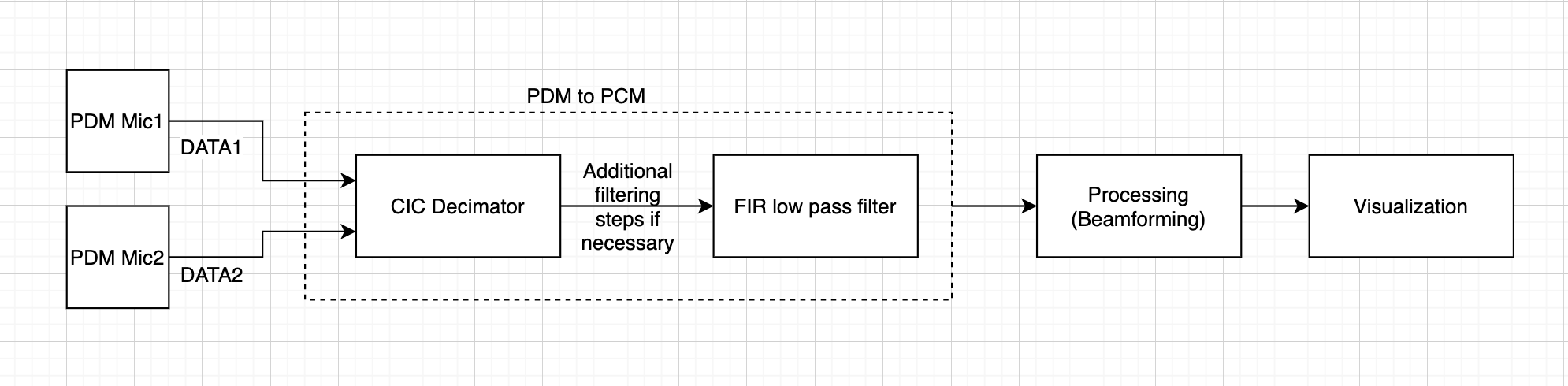
If we average (low pass filter) the PDM signal in blue, we’re able to recover the original analog signal. Implementing a low pass filter with discrete analog components is one way to recover the audio, but since we’re dealing with 96 microphones, we want the processing to be digital for greater flexibility and we don’t need ADCs as well.

If performance turns out to be an issue, we will look into more efficient low pass filter algorithms such as using cascaded integrated-comb filters.

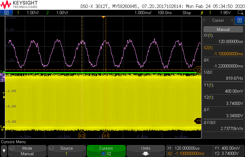
As a quick sanity check, we were able to probe the output of the PDM microphone and apply the scope’s low pass filter to get the signal back:

Ryan’s Status Update for Saturday, Feb. 29

This week we focused on our Design Review Presentation.  The format was similar to our Proposal Presentation, but this time, we focused on the specifics of the implementation and zeroing in on our metrics and requirements.

We narrowed down on our use case for the Sonic Imager; we’re going to use it to detect air leaks in pneumatic systems. Before, we packaged this as a general purpose audio to image conversion device, but we agreed that having a specific use case would help us focus on achieving metrics related to it, as opposed to being mediocre at everything.


John and I were able to test the basic operation of the PDM microphone. The Teensy 4 was providing a 1MHz clock to the PDM mic, and was receiving the digital output from it. We played an 820Hz tone from my phone, and when we probed the output, we were able to see a pulse density modulated signal. Using the scope’s built in low pass filter, we were able to recover the 820Hz tone: (PDM output in yellow, LPF signal in purple)

I’m currently working on a script to convert the PDM output into PCM audio. I first started writing the script in Python, but I’ve run into issue with signal visualization and plotting on my environment (Ubuntu WSL on Windows and TKInter).

I’ve decided to switch to MATLAB for its versatile graphing options, although it may take more time to write code. I plan to finish the script tomorrow.

Here’s 500 samples (about 0.5ms) of PDM output plotted:

The method of converting PDM to PCM is to create a low pass filter, and MATLAB has a nice library for that.

We are on schedule, and next week I’ll see if there are higher performance and time-efficient filters to speed up processing. CIC filters perhaps?

Sarah’s Status Update for Saturday, Feb. 22

This week, I worked on processing PDM signals into PCM and processing analog into PDM. Both of the work was done since we want to have flexibility in handling different data. The coding was done in MATLAB since we wanted to have a quick code for simulation and testing purposes. However, later on, we will be writing the program in either Java or Python for efficiency and higher level processing steps.

This is a block diagram for how the received signals will be processed.

The relative density of pulses of the audio data is represented in PDM signals. I used a sawtooth wave to modulate the analog signal to output PDM. However, I realized this is PWM output, which is a special case of PDM, but quite different from what we want to achieve. PWM signal is when the switching frequency is fixed. Now, I instead will approach to  modulate the analog signal with a binary signal to produce PDM signal.

In converting the PDM signals to PCM signals, I am first sampling at a lower rate (method called Decimation) and going through a series of FIR low pass filter (3rd order FIR possibly), making sure the information signal within the  bandwidth of interest is captured. More research should be done in this area.

What to do next:

  • Edit the code and make sure it works.
  • Test analog to pdm and pdm to pcm with sample data.
  • Think about higher level processing and try writing the code.


Jonathan’s Status Update for 2/22

This week I mainly worked on getting the gigabit ethernet interface working on a development board, and, put together a board for testing the PDM microphones.

After getting the FPGA toolchain set up last week, I spent most of this week putting together a basic RGMII interface.  A significant amount of the time spent was on the IO.  Since RGMII is a relatively fast DDR interface, in order to meet timing, I had to use ODDR2 blocks for all the pins.  I had never used these before, and had some initial difficulty getting them to work as expected.  Additionally, some of the IO that I was using to verify operation were buffered with 74HC245 bus transceivers, which cannot operate at the 125MHz required for RGMII.  Once I realized that they were to blame for some of the unusual behavior, I removed them from the board and bypassed their footprints with wires.  At this point, the board is able to send a hardcoded UDP packet over the RGMII interface, however, the PHY does not transmit it.  I am not sure whether this is because some additional configuration is required for the PHY, the RGMII is not being generated correctly or something else, and, cannot find a datasheet for the PHY.  I’ve emailed Broadcom, but haven’t received a reply.  Last week I got a sample of a PHY from Analog Devices, which does have a datasheet available online.  If I’m unable to get the broadcom PHY working, I will probably either use the AD PHY, or purchase a breakout board for a different chip (several are available online for ~$40).

I also built a basic breakout board for one of the PDM microphones, and wrote a basic interface using a Teensy 4.0, that sends the raw PDM data over USB.  I did not have time to do any analysis on this data, however.

(close up of the microphone)

(microphone test board.  Dip switches for switching between multiple microphones)

No significant changes to the plan have occurred, and we are still on track.  Our main risk of falling off-track will be that I will have to get at least a basic ethernet interface working, or else pivot to a different interface, within the next week.

This coming week, I plan to mainly work on the ethernet interface.  I’ll be handing off the PDM microphone test board to Ryan and Sarah, going forward, for audio properties and testing data processing.

Team Status Update for Saturday, Feb. 22

Currently the primary risks are:

  • Not being able to get the gigabit ethernet working.  Managing this mainly by addressing it first,as it’s likely to be one of the most challenging parts of the project.  If we’re unable to get it working, it’s best to know soon so we can switch to another interface as soon as possible.  Current primary contingency plans are:
  1. Use a Zynq board.  The Zynq chip has a built-in gigabit MAC, and, many reference designs using it.  This moves the complexity from this to setting up the Zynq itself, though that will most likely use existing tools from the vendor.
  2. Use a USB interface.  Either a fast micro controller with a USB interface such as the Teensy 4.0, or one of several development boards specifically designed for simple, high-speed USB interfaces, such as the CYUSB3KIT.
  3. Use an off-the-shelf board that already has an working example written for it, such as the Mimas A7 from Numato.
  • Some aspect of the microphones renders then unsuitable for this project.  We are managing this risk, again, by tackling it early.  We have already ordered some sample microphones from Digikey and rigged up a testing board in order to run some basic tests and get some hands-on experience with PDM, since none of us have ever used it.

The overall design is unchanged from the previous update.

Ryan’s Status Update for Saturday, Feb. 22

Termination resistors?

Since the signals going in and out of the PDM microphones are digital, termination  resistors may be needed to reduce ringing and overshoot when the signal is being transmitted over a long distance. TDK’s recommendation is as follows:

When long wires are used to connect the codec to the ICS‐41350, a source termination resistor can be used on the clock output of the
codec instead of a buffer to minimize signal overshoot or ringing. Match the value of this resistor to the characteristic impedance of
the CLK trace on the PCB. Depending on the drive capability of the codec clock output, a buffer may still be needed, as shown in Figure
13.

From: https://43zrtwysvxb2gf29r5o0athu-wpengine.netdna-ssl.com/wp-content/uploads/2016/02/DS-000047-ICS-41350-v1.1.pdf


Let’s do some quick calculations if termination resistors are required at these signal speeds. Here’s a paper that discusses when it’s necessary to put termination resistors: https://www.analog.com/media/en/training-seminars/tutorials/MT-097.pdf

The maximum PCB track length is then calculated by multiplying tr by 2 inch/nanosecond. For example, a maximum frequency of 100 MHz corresponds to a risetime of 3.5 ns, so a 7-inch or more track carrying this signal should be treated as a transmission line.

We’re driving the input clock to the PDM microphones at 3.0MHz. At 3.0MHz, the rise time is about 115ns. The dimensions of the microphone array are 1x1ft max, so the maximum FFC cable length is 1ft. 115ns * 2 in/ns is 230in, so we should be at least an order of magnitude safe without termination resistors.

  • We haven’t heard back from TDK or Knowles regarding microphone samples, so I’ll follow up next week. Even if we don’t get the microphones for free, we still do have enough budget for them. ($150 for 100 mics)
  • We will have our design review on Monday, Feb 24, so we’ll be preparing for the presentation.
  • We are on schedule so far.
  • To do: Solder wires to the microphones, power it with 3.3V and feed it a 3MHz clock. Capture the output waveform from the mic and develop a script to analyze the waveform. Low pass filtering it should yield the analog waveform.

Jonathan’s Status Update for 2/15

What did you personally accomplish this week on the project? Give files or photos

This week I mainly did simulations of different array geometries, microphone quantities, and spatial distributions.  More of these images are in the team report, but a specific result of note is shown below:

This was a simulation of a single point source set to 4,6,8, and 10 KHz for each set of images, with a 8″x12″ array of 96 microphones.  The upper set of 4 images shows a regular rectangular grid arrangement, and shows clearly visible repeated artifacts (sidelobes) that also appear in a similar grid pattern.   The lower set of images shows microphones randomly distributed in the same space.  In this case, the main lobes are essentially unchanged, but the distinct, repeated artifacts are replaced with a much more macroscopically uniform noise.  The hope was, that removing the periodic spatial component of the array would spread out the sidelobes more evenly throughout the entire image.  Since some areas in the first images have noise floor to spare, it seems that it may be possible to spread the artifacts out into these areas, reducing their peak amplitude at the expense making them larger spatially.  The random distribution did spread out the artifacts almost completely evenly over the entire image, but, did not significantly reduce the peak amplitude, which was the whole point.  We will likely take another look at doing something like this (altering geometry to reduce artifacts) later on in the project, but for now, we plan to move forward with the rectangular array of 96 microphones, as initially planned.

I also set up the xilinx toolchain for a board I already owned, which we plan to use to do some initial proof-of-concept testing for the gigabit ethernet interface.  We expect that to be one of the more significant technical hurdles of the project, and want to get some experience with it before coming up with the final design.  I didn’t have enough time to actually get the ethernet driver working, but, was able to, after some initial difficulties, program the fpga with a basic program.

With our change to primarily pursuing PDM microphones instead of analog microphones, several components of the plan have changed, but, we are still on track under the new plan.

This coming week, I plan to do some basic, proof of concept testing of the GbE interface, to make sure that it will work for our project before we fully commit to that.  I also plan to begin design of the PCB to interface the FPGA board to the microphones, but I do not expect to finish it this week.  If any of the microphones we’ve ordered show up within the week, I plan to begin some experiments and proof-of-concepts with those.

Sarah’s Status Update for Saturday, Feb. 15

The output of the digital microphone is a pulse density modulated (PDM) signal. More information regarding why we are leaning towards using these microphones can be found in Ryan’s Status Update for Saturday, Feb 15.

PDM uses pulse density to represent a signal where ‘1’ is positive polarity and ‘0’ is a negative polarity. Simply put, it is a oversampled 1-bit audio. Raising the analog input signal makes more 1’s in the output bit stream and lowering results in series of 0’s.

This week, I was able to research about how decoding and processing works for PDM microphones. First off, converting PDM to analog form can be simply done through low pass filtering. The low spectrum of the PDM signal contains the audio already.

On the other hand, in order to process the PDM signal, we need to convert it into PCM.  Through the process of Decimation, a digital filtering operation where samples are removed from the signal to reduce the sampling rate, we want to output at a non-oversampled rate.

For phased array techniques, I am initially working on Delay and Sum Beamforming (DSB) which is the simplest of all beamforming techniques. DSB allows amplifying signals from a specific direction while suppressing other signals.  In the frequency domain, we apply a phase delay to the frequency spectrum of each array element, and sum all the delayed spectrum.

What to do next week:

  • Write and work on array processing tests/simulations and get results.

Sources:

https://www.sciencedirect.com/topics/engineering/delay-and-sum-beamforming

https://pdfs.semanticscholar.org/aaab/c78c41d0fdcc8c83247f9f0974de98349fb3.pdf

https://www.mathworks.com/help/supportpkg/stmicroelectronicsstm32f4discovery/ref/micin.html

 http://users.ece.utexas.edu/~bevans/courses/rtdsp/lectures/10_Data_Conversion/AP_Understanding_PDM_Digital_Audio.pdf 

Team Status Update for Saturday, Feb. 15

What are the most significant risks that could jeopardize the success of the project?

The largest challenge so far is:

making the final decisions on the array shape and size, as many aspects of the system will be depend strongly on this.  How are these risks being managed? What contingency plans are ready?

• Were any changes made to the existing design of the system (requirements, block diagram, system spec, etc)? Why was this change necessary, what costs does the change incur, and how will these costs be mitigated going forward?

We have the results of several simulations of different array geometries, sizes, and frequencies of interest.  In all cases, they are attempting to image a scene with a single source at a specific frequency.  Plots are 4 separate images of the same scene at different frequencies, but all other parameters are the same.

Randomly distributed microphones, showing slightly reduced artifacts, but at the cost of a higher, random noise floor over most of the image

Image form microphones randomly distributed through a volume, showing nearly identical performance to the random array

8*12 rectangular array images, showing better noise performance over most of the image than the random distribution, but with distinct, clearly visible artifacts.

Early, low-resolution simulation, showing that the concept is at least viable at these sizes/frequencies.

The 10KHz image in this series shows one of the issues with higher frequencies, an artifact is visible at the left of the image, while the source is slightly off center to the right.  This artifact stays out of the field of view that we’re interested in (90 degrees), but will have to be considered in the final design.

Ryan’s Status Update for Saturday, Feb. 15

This week, we’ve evaluated candidates for PDM microphones, which take in a 3MHz clock and output a pulse density modulated digital signal, as shown below: 

Source: https://en.wikipedia.org/wiki/Pulse-density_modulation

The reason why we’re leaning towards PDM micrphones as opposed to analog microphones is because since PDM microphones output a digital signal, we don’t need preamplifiers and ADCs for the analog microphones, and they can be directly connected to an FPGA. The price difference between analog and digital microphones are negligible.  When we’re looking at about 100 microphones, reducing the number of parts greatly reduces cost and complexity.

The two main manufacturers of PDM microphones are TDK and Knowles. I’ve reached out two both companies to see if they’re willing to help us get hold of their PDM microphones. So far, their responses have been positive and willing to work with us.

The main spec that we’re looking in the PDM mics is frequency response. Because we’re interested in 2kHz and beyond, having a relatively flat frequency response is critical to our application. The frequency response information can be found in their respective datasheets. Here’s an example from TDK’s ICS-52000:

Source: http://43zrtwysvxb2gf29r5o0athu-wpengine.netdna-ssl.com/wp-content/uploads/2016/05/DS-000121-ICS-52000-v1.3.pdf

Notice how after 5kHz, the amplitude starts rising and peaks at 12kHz at 18dB. It drops precipitously after that. This is an example with a poor frequency response. This may be good enough for cellphones where frequencies above 8kHz or so are not transmitted, but isn’t ideal for our application.

Here’s the SPH0641LU4H-1 from Knowles. It has a slightly more well behaved frequency response at higher frequencies:

We’ve ordered a sample of of microphones to further investigate their characteristics and identify areas of focus regarding these microphones.

We are on schedule.

To do next week:

Continue communication with Patrick from TDK regarding PDM mics from them as well as logistics. (QTY and shipping to us or the PCB fab)

Receive PDM microphone samples and solder and interface them with MCUs or FPGAs for testing.

Start designing the PCB for microphones. Draft a list of auxiliary components for the mics. (Termination resistors, decoupling caps, LDOs)