The output of the digital microphone is a pulse density modulated (PDM) signal. More information regarding why we are leaning towards using these microphones can be found in Ryan’s Status Update for Saturday, Feb 15.
PDM uses pulse density to represent a signal where ‘1’ is positive polarity and ‘0’ is a negative polarity. Simply put, it is a oversampled 1-bit audio. Raising the analog input signal makes more 1’s in the output bit stream and lowering results in series of 0’s.
This week, I was able to research about how decoding and processing works for PDM microphones. First off, converting PDM to analog form can be simply done through low pass filtering. The low spectrum of the PDM signal contains the audio already.
On the other hand, in order to process the PDM signal, we need to convert it into PCM. Through the process of Decimation, a digital filtering operation where samples are removed from the signal to reduce the sampling rate, we want to output at a non-oversampled rate.
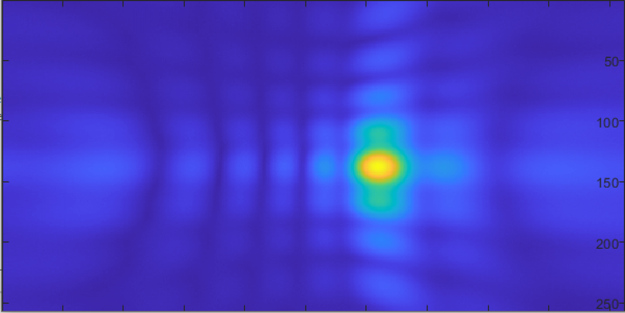
For phased array techniques, I am initially working on Delay and Sum Beamforming (DSB) which is the simplest of all beamforming techniques. DSB allows amplifying signals from a specific direction while suppressing other signals. In the frequency domain, we apply a phase delay to the frequency spectrum of each array element, and sum all the delayed spectrum.
What to do next week:
- Write and work on array processing tests/simulations and get results.
Sources:
https://www.sciencedirect.com/topics/engineering/delay-and-sum-beamforming
https://pdfs.semanticscholar.org/aaab/c78c41d0fdcc8c83247f9f0974de98349fb3.pdf
https://www.mathworks.com/help/supportpkg/stmicroelectronicsstm32f4discovery/ref/micin.html