Sarah’s status report for Saturday, Apr. 25

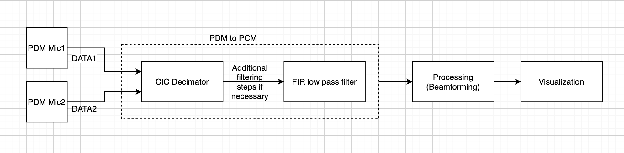
This week, I worked with Ryan to build delay and sum beamforming without the use of external libraries provided from MATLAB.

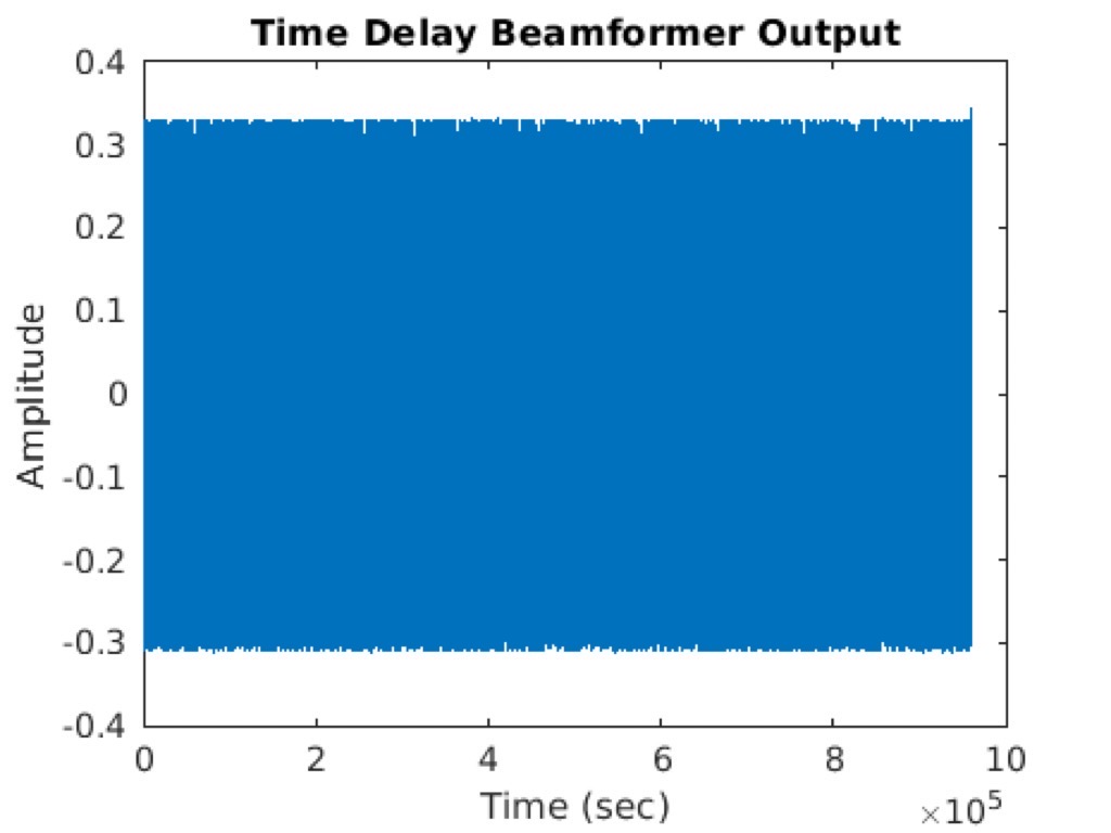
This beamforming allows amplifying signals from a specific direction while suppressing other signals. This conventional method of beamforming provides ease of implementation. The method has been used widely for processing arrays. A disadvantage would be in low resolution in closely spaced targets. However, as long as we are able to detect the source of the leak for our project, this is acceptable. Several steps were taken to achieve the output. First off, signals captured in microphones have similar looking waveforms but include delays. I calculated the delay with the fact that we know the angle, distance between the microphones, and distance from the sound source. By simple geometry and algebra with polar coordinates, I was able to get  x,y and z for distance and divided by the speed of sound to get the delay. Two other delay calculation methods were also taken but, the results were better shown for the current method. Then, the signal of each microphone was shifted by an appropriate delay amount. The shifted microphones were then summed up and normalized by the number of microphone channels. 

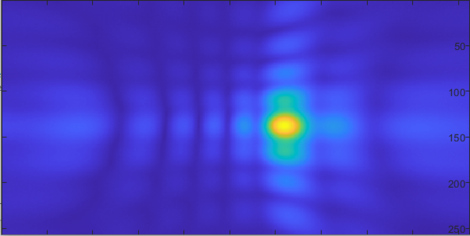
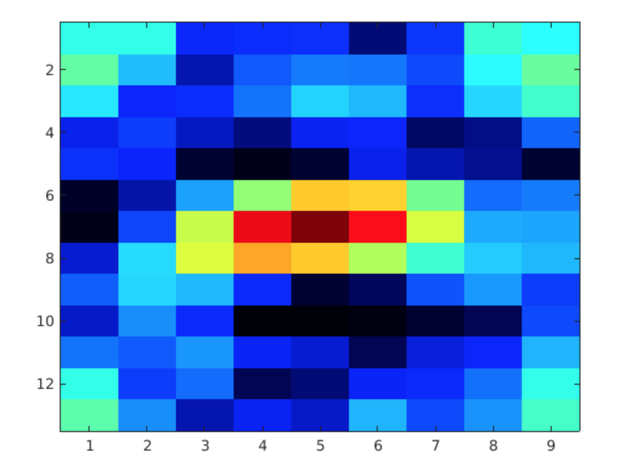
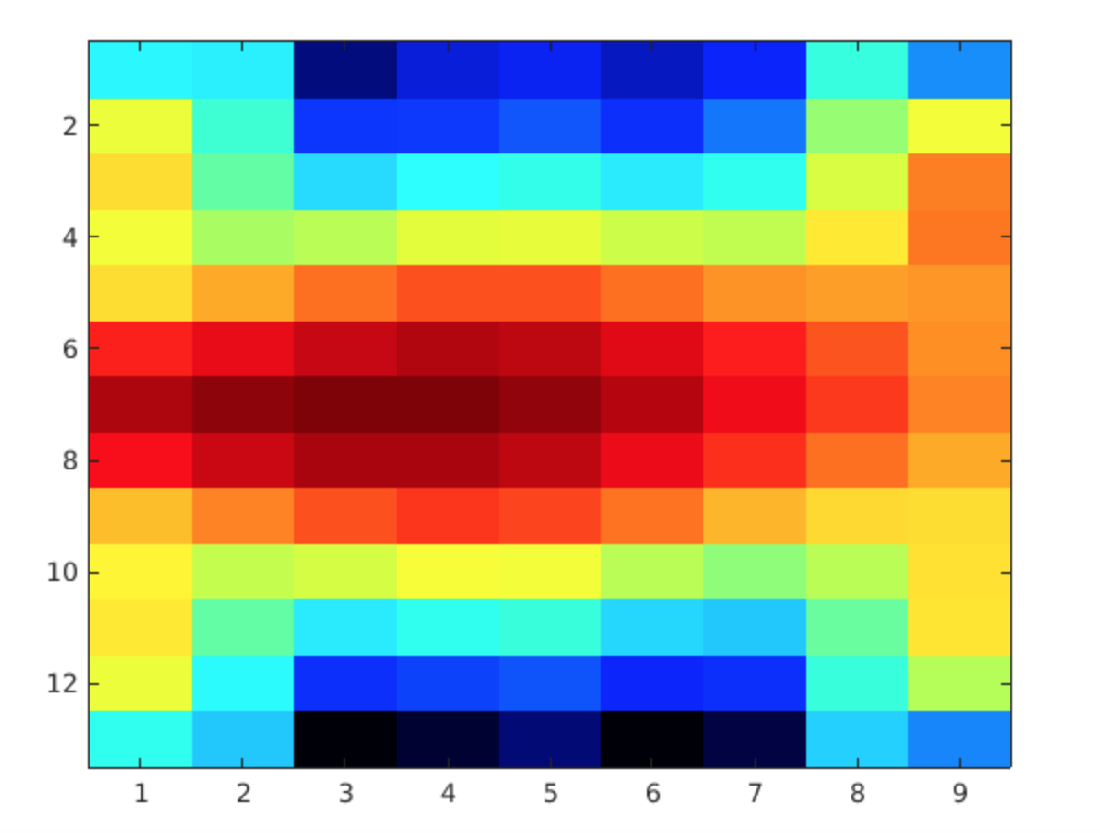
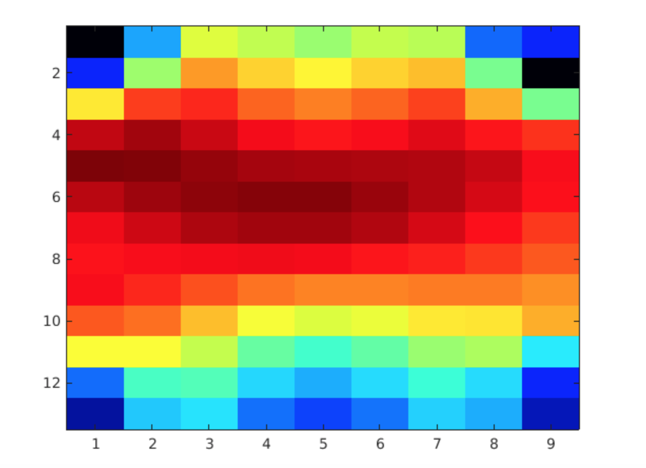
Visualization of the beamforming output was simply done through a heatmap. Sound source regions were shown in brighter colors. The resolution ended up to be low, but an approximate location can still be visible through the heat map. 

2k Gaussian (source from center) 

Synthesized Leak (source slightly off center to the left)

Real Leak (source slightly off center to the left)


Next week, I will work on the final report with my teammates!

Sarah’s Status Report for Saturday, Apr. 18th

This week, as the network driver started to work, I received several logfiles from John. The logfiles were revised with headers that included information about the length of the data, logfile version, time start of recording, and location of errors. The recording was from a 4×4 array with the logfile including some real data and some chunk of non-real data. I worked on outputting wav files from the pdm data but faced an error in hex to bin conversion. I believe that major problems may have been due to minor changes in the logfiles. As the length of the data is given now, it may be helpful to use the number and not hard code which we previously did.

Next week, I will make sure the error get fixed and have the output. Hopefully, the output matches the results that John received through real-time processing.

Sarah’s Status Report for Saturday, Apr. 11

This week, we presented our midpoint demo. The demo went well with the visualization of a sound source in real-time. I also worked on writing the existing code into python. Since we found that the logfiles we were working with possibly had errors, I didn’t move on to the localization of sound source since making sure the existing processing worked was important. As I have received new logfiles for simulation, I believe the results will be better shown compared to last time.

Next week, I look forward to doing some testing with the logfiles to see if the output looks as we assumed. If there is time, I will be working on visualizing the sound source.

Sarah’s Status Report for Saturday, Apr. 4

This week, I mainly worked on time-domain delay and sum beamforming. I was able to make the simulation output. I received a 5khz and 10khz log files from John and processed for 96 channels, 8 by 12 array and 1-inch spacing parameters. The output is shown below.

However, I realized later that the logfiles are actual data from just 2 microphones. After adjusting to the correct parameters, the resulting output was below which didn’t seem to match out the assumption that there should be a single spike at 5khz. Major problems and problem fixes can be found in John’s Status report.

For next week, I will focus on writing a visualization for a heat map for the data.

Sarah’s Status Report for Saturday, Mar. 28

This week, I mainly worked on writing up time delay beamforming processing.

For a linear array of microphones that are located perpendicular to the sound source, the signals captured by the microphones have similar wave forms but varying delays. In order to account for these delays, I calculated it from speed of sound, distance between the microphones and the sound sources. Also, signals must be shifted for runtime difference. Finally, all the signals can be summed up. The summed signal is then normalized by the number of microphone channels.

For next week, I plan to run simulations with sample data and fix any problems that come up.

Sarah’s Status Update for Saturday, Mar. 21

This week, I had a meeting with my team members and Professor Sullivan to talk about modifications in our project. Since my team will have to work on the project remotely for the rest of the semester, we have to break up the parts so that the workload is evenly divided to each person. We are thinking to have Ryan collect audio date from the microphone array and pass it to John for processing and then finally passed to me for localization. There need to be more discussions on the plan for the upcoming week. In addition, I worked on coding PDM to PCM in Python. I also researched about localization of audio sources in Python as well.

Our schedule will need to be modified due to the remote working environment. Yet, I am still on track with the major components.

Next week, I will have more discussions with my team members and work on debugging python code.


Sarah’s Status Update for Saturday, Mar. 14

Before heading off for Spring break, there were some updates.

I worked on finalizing PDM to PCM code with help from Ryan. The FIR low pass filter I used has a large order which has a narrow transition band. The image below shows our filter.

The image below shows the filtered PDM signal using the FIR filter.

It shows that there is high-frequency content, critical for identifying our sound source. I plan to test more pdm data for similar results.

I also worked on the design report with my members. We received feedback from Professor Sullivan and will further discuss the details through our meeting.

We are on track and there are a few things to do this coming week as planned.

To do next:

  • Discuss with my team members about re-scoping the project and make design decisions due to a change in our locations.
  • Discuss design report feedback with members.
  • Work on pdm to pcm in Python.


Sarah’s Status Update for Saturday, 29 2019

This week, I presented the Design Review Presentation. We focused on specifying the metrics and validation of our project.  Many helpful feedbacks were given by the audience. After receiving peer review feedback, I personally learned how I presented in front of people. I realized that I lacked skills in speaking loudly and having eye contact with the audience. The feedback also included some specific comments about our design as well. We are looking forward to covering the feedbacks on including array geometry and simple frequency analysis for our design report. The comments were very helpful.

(output of analog to pdm with simple signal)

In addition, I created analog to pdm converter as shown above. The code can used for testing purposes. Furthermore, a basic pdm to pcm is coded with the help from Ryan. He found a nice library in MATLAB that had the necessary functions to do so. The plot can be seen in Ryan’s Saturday Report. Yet, we do have considerations that the current code is not efficient enough for 96 microphone array. Some more filtering should be done.

A potential solution is found to be using a CIC filter. CIC filters achieve both decimation and interpolation without using multipliers.  We find this a good alternative to the current design of pdm to pcm.

In terms of the schedule, we are on track.

For next week, I look forward to starting coding in Python or Java since we are currently working on MATLAB codes and look for efficient manners of computing the pdm to pcm.

Sarah’s Status Update for Saturday, Feb. 22

This week, I worked on processing PDM signals into PCM and processing analog into PDM. Both of the work was done since we want to have flexibility in handling different data. The coding was done in MATLAB since we wanted to have a quick code for simulation and testing purposes. However, later on, we will be writing the program in either Java or Python for efficiency and higher level processing steps.

This is a block diagram for how the received signals will be processed.

The relative density of pulses of the audio data is represented in PDM signals. I used a sawtooth wave to modulate the analog signal to output PDM. However, I realized this is PWM output, which is a special case of PDM, but quite different from what we want to achieve. PWM signal is when the switching frequency is fixed. Now, I instead will approach to  modulate the analog signal with a binary signal to produce PDM signal.

In converting the PDM signals to PCM signals, I am first sampling at a lower rate (method called Decimation) and going through a series of FIR low pass filter (3rd order FIR possibly), making sure the information signal within the  bandwidth of interest is captured. More research should be done in this area.

What to do next:

  • Edit the code and make sure it works.
  • Test analog to pdm and pdm to pcm with sample data.
  • Think about higher level processing and try writing the code.


Sarah’s Status Update for Saturday, Feb. 15

The output of the digital microphone is a pulse density modulated (PDM) signal. More information regarding why we are leaning towards using these microphones can be found in Ryan’s Status Update for Saturday, Feb 15.

PDM uses pulse density to represent a signal where ‘1’ is positive polarity and ‘0’ is a negative polarity. Simply put, it is a oversampled 1-bit audio. Raising the analog input signal makes more 1’s in the output bit stream and lowering results in series of 0’s.

This week, I was able to research about how decoding and processing works for PDM microphones. First off, converting PDM to analog form can be simply done through low pass filtering. The low spectrum of the PDM signal contains the audio already.

On the other hand, in order to process the PDM signal, we need to convert it into PCM.  Through the process of Decimation, a digital filtering operation where samples are removed from the signal to reduce the sampling rate, we want to output at a non-oversampled rate.

For phased array techniques, I am initially working on Delay and Sum Beamforming (DSB) which is the simplest of all beamforming techniques. DSB allows amplifying signals from a specific direction while suppressing other signals.  In the frequency domain, we apply a phase delay to the frequency spectrum of each array element, and sum all the delayed spectrum.

What to do next week:

  • Write and work on array processing tests/simulations and get results.

Sources:

https://www.sciencedirect.com/topics/engineering/delay-and-sum-beamforming

https://pdfs.semanticscholar.org/aaab/c78c41d0fdcc8c83247f9f0974de98349fb3.pdf

https://www.mathworks.com/help/supportpkg/stmicroelectronicsstm32f4discovery/ref/micin.html

 http://users.ece.utexas.edu/~bevans/courses/rtdsp/lectures/10_Data_Conversion/AP_Understanding_PDM_Digital_Audio.pdf