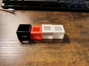
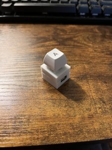
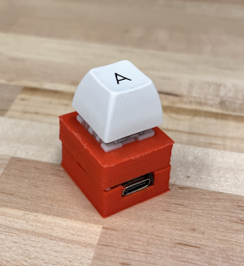
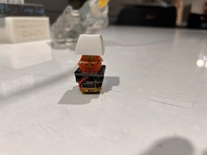
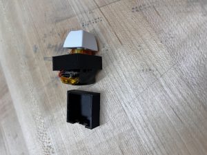
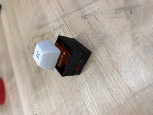
We completed the project! April Fool’s haha…
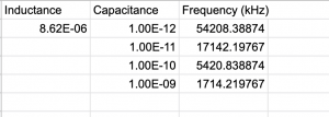
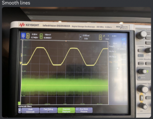
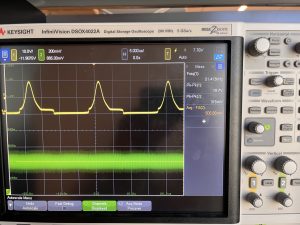
This week was quite a bit of debugging for the inductive charging kits, in conclusion we have determined that the kits are specifically tuned to the inductance and resistance of the kit coils. While understandably so, we have been swapping out the resistors and capacitors on the board to make our own observations on what each component has in relation to the inductance values, in which case we are quite stuck on. The board has capacitors that are not seemingly tuned to resonance so this makes it more difficult to determine what changes are needed to be done.
The inductive kits are made of a power amplifier and an oscillator, we haven’t found a direct relation as to what the changes are. We compared with sample schematics but even when replicating a schematic, it was not attuned to the stated inductance but still to the 30uH. We tested with various resistors, capacitances, and creating new coils.
We may look to buying products that fit our size, but may need to lengthen the housing more, however it would be good to have a meeting in order to sort out what could be done with the pcb kits we have.
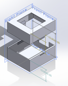
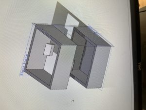
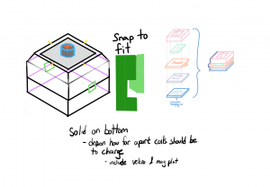
As for 3D housing, because most of time was spent on figuring out the inductive kits, that is a bit behind, but I plan on printing the changes on Sunday. I added the top cover, adjusted the wall widths, added a USB-C hole, and compacted the width of the total housing to be thinner on one side, however, the other will stay the same.
