Accomplishments this week
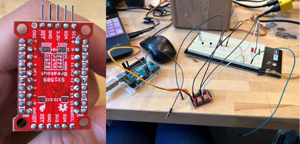
This week I tested out a different option for our I2C motor system driver. The new board I tested was the SparkFun 16 Output I/O Expander Breakout – SX1509. The voltage level and current were lower than the Adafruit servo driver, but this board only needed two wires to run a PWM device. However, through testing, I found that the Adafruit device provided a better option as a motor system driver.

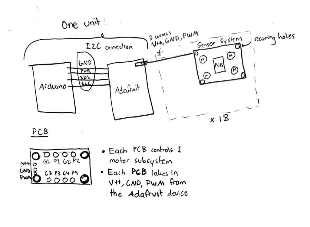
After deciding on a motor system driver, I was finally able to begin a PCB design which would take the PWM signal, V+, and GND from each motor driver output of the Adafruit device and transform that PWM into a voltage level to drive each motor in the motor system. In the original drawing, the plan was to have up to 4 outputs for the possible 4 motors each motor system would run. Amelia then brought up that we might be able to get around this by soldering the ends of the motors together so the PCB would only need one variable V+ output and GND output for the motors. The final design will have the Arduino and Adafruit device close together on the vest. Because these two devices take up the most room (header pins facing outwards), this will limit the bulkiness in the overall vest design. There will then be 16 sets of PWM, V+, GND pins coming out of the Adafruit device going to 16 of the 18 motor subsystems.

I found a basic PWM to DC voltage conversion online (https://www.egr.msu.edu/classes/ece480/capstone/spring15/group10/Application%20Notes/Kyle.pdf) and began to implement it in Fusion 360 to get a feeling for the tool. I was able to implement the design and discuss with Amelia what the best layout for the PCB would be.

Schedule update
On Sunday, I plan to do some circuit analysis on the current PWM to DC voltage converter. I plan to research which opamp will fit the project the best and go through the problem to figure out the other parts we should need. I will also continue to work on the motor code which I deviated from this week in order to focus on the PCB design.
Deliverables for next week
I hope to check with Professor Fedder and Omkar on the PCB design before sending out an order. I will then have to go onto DigiKey or a similar website to order the opamps, resistors, capacitors, and other components for the PCB.
