
Accomplishments this week:
Last week I planned to focus on creating the motor control algorithm due to the uncertainty of getting parts in. On Monday, along with working on our block diagrams and user survey on our physical input system, I worked on my motor control algorithm. This included looking into how the Adafruit I2C device would control the outputs and also how to create classes in Arduino. Amelia was able to test a vibration motor with the Arduino and found it worked with the Arduino’s PWM pin with sufficient vibrational feedback. Testing the motors further would have to wait for the servo driver.
Algorithm: The main issue I found with creating the Response class in Arduino is that I need to come up with a way to make variable sized arrays. The arrays will hold which motors I want to activate for each “wave” of a haptic response. I figure I can either initialize longer arrays that I’ll need then be required to fill with -1’s for the unused indexes, or I can create some sort of variable length char array. Hardcoding various haptic patterns is also an option, but I’d like to make something more variable. However, for initial testing purposes, hardcoding to ensure the variable sized array isn’t causing a bug might be a good starting point. This left me at a point where I would have to know more about the I2C device to successfully use the functions.

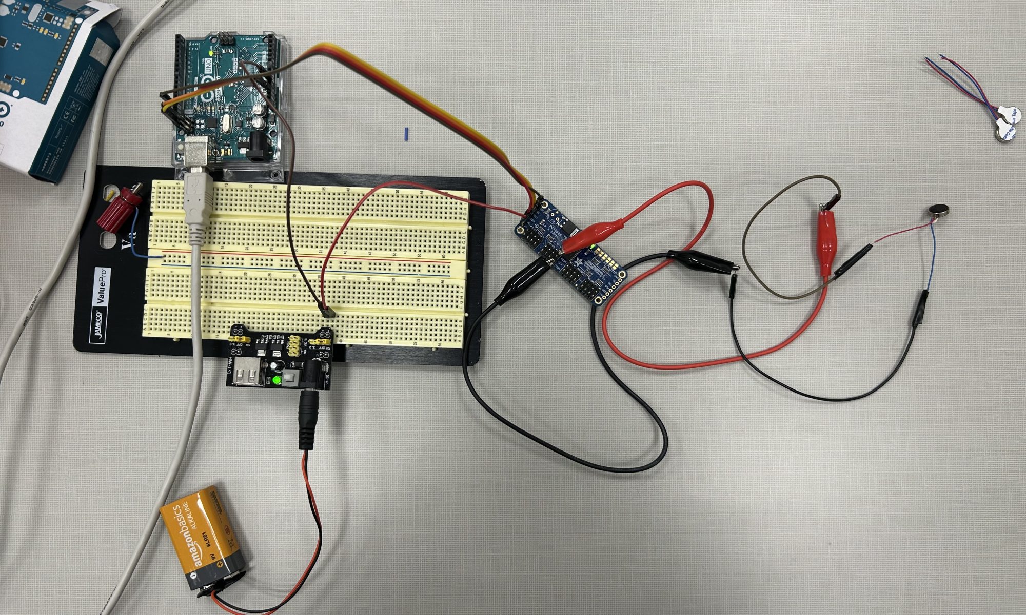
Soldering and I2C: Thankfully and unexpectedly, the I2C servo driver and the motors came in on Tuesday. This allowed me to spend Wednesday relearning how to solder so I could solder the header pins onto the servo driver PCB. This, along with doing some tasks with my team, took most of the class. I ended up finishing the soldering on Friday. I then proceeded to test the vibration motors when they are connected to the I2C device. I did come across some minor issues using the I2C device: the motors don’t seem to run. I used my good old 18-100 debugging circuit skills to try to figure out what was going wrong. The device is set up so there are the GND, SLC, SDA, and VCC pins coming in from the Arduino which provide the signals for the device. Then there is a V+ pin which is connected to a different 5V power supply to supply voltage to the motors. I was able to wire up the I2C device so when I run code to turn on and off an output, you can measure the changing voltage with a multimeter. And I also had some basic servo motors from 18-100 which did move when the code was run. However, the small vibration motors–despite me being able to read a voltage up to 5V from the PWM to GND pins–did not buzz.

Other Stuff: I also worked with Amelia and Bethel on our Design Report presentation. (Saturday night update: a lot. We worked on the design report presentation a lot). The design report required multiple schematics and wiring diagrams that took a while to design.
Updates on my schedule:
I am currently on schedule. With the change with the physical input device, my schedule has changed a bit, but my two main tasks of creating the motor algorithm and driving the motors from the servo driver are still on schedule. Although I am going to switch up my schedule because I want to get the motors working properly before moving forward with the algorithm. I believe this will allow me to better understand what functions and parameters the algorithm needs to control.
Deliverables for next week:
Next week is pretty busy for me in most of my classes, but I plan to have some basic working code so specific motors can be signaled to turn on and off given some power and time_on values. This requires me to debug why the power I’m providing to the motors does not cause them to vibrate. Once I have basic function to run one motor, I can easily add them to an class function in Arduino so I can run multiple motors at the same time and in a specific pattern.
List the particular ECE courses (if any) that covered the engineering science and mathematics principles your team used to develop your design
I used 18-100 and 18-220 for the principles on how to set up I2C connections and debug circuits. These classes allowed me to design my system so the ground from the I2C power source was connected to the ground of the Arduino. This is required so they are in the same circuit and weird different-circuit errors don’t occur. I also believe 18-100 had a soldering lesson freshman year so that helped me with soldering the header pins onto the servo drive PCB this week. I’m also using 15-112 principles for designing my algorithm and creating a class in C++. I think the reason I’m using all my freshman year courses is because it is in those classes I learned the basics of engineering which can be generalized a lot easier than later courses. A lot of my later courses allowed me to improve upon those generalized skills while specializing in other areas. However, most of those specialized skills may not come into play with this project, hence the focus on earlier classes.