Breyden Wood’s Status Report for 5-8-21

This week, I spent the majority of my time preparing for the final presentation I gave on Wednesday of our project. This process required me to flesh out all the slides and review what I was going to say in a couple practice runs for our group. Overall, I was very happy with how the presentation went and I feel we got good feedback from the course staff on ideas for our final video.

After working on the presentation, I transitioned to fleshing out some bugs in our background removal. By working on the angle of the LEDs on the sides and fine-tuning the parameters on the FPGA, I was able to get an excellent result with the majority of the objects that we tested where all the background would be removed with minimal clipping on the object.

Lastly, I have worked on collecting footage both explaining the FPGA’s inner workings and filming lots of B-roll of our entire setup. All that is left for me to do is to assist Jullia in editing all of this together into a demo video that we are all happy with. Our progress is on track, and we expect to be finished with all of our work in the coming days.

Breyden Wood’s Status Report for 5-1-21

This week, I worked on integrating the entire pipeline together. I went over to Jullia’s place where the entire setup is currently assembled. Jullia and I worked together to set up the TV and the pyramid by moving the TV flat on the table. I also mounted the cameras into the studio after the holes in the studio were cut out. There was some adjustment needed after the cameras were mounted into the studio regarding the orientation of the video footage. I adjusted these issues through Quartus so that the video footage faced the correct direction and displayed correctly on the pyramid and TV setup. Testing also revealed some memory bugs with lines of incorrect colors showing at the bottom or top of the square of projected images. I resolved this error by changing the SystemVerilog code to remove these lines.

Some of the cameras also needed to be switched out due to differences in auto-exposure and white balance. This was previously identified as an issue last week, and we were able to fix it with the new cameras we purchased this week. As mentioned in the Team’s status report, longer wires resulted in greater electrical noise, so we had to place the FPGA and Arduino at the bottom of the pyramid (instead of above it). The wires are extremely sensitive and any slight adjustment of the studio results in the wires getting loose. This creates a lot of noise on the video feed and I have had to adjust these connectivities using tweezers from time to time.

I spent the bulk of my time adjusting lighting and the parameters for the chroma key algorithm to ensure optimal background removal (with a uniform background). As synthesized, the chroma-key algorithm takes in an RGB value and threshold setting for sensitivity. I carefully adjusted the RGB values while adjusting the lighting for the studio for the evenest lighting and best possible background removal.

I also captured video footage of our project using my personal camera and tripod. I took wide-angle shots, video footage, and close-up photographs. This footage will be used in the final presentation as well as the later final demo. I also did latency testing using the remote for the studio lighting, determining that our project has ~21 ms of latency (much better than our initial requirement of several hundred ms).

I am on track with our schedule. The project is fully integrated, testing has been started, and I have taken extensive amounts of footage for our final video. Over the next day, I will practice the final presentation, which Grace and Jullia will provide feedback on. Over the next week, I will work with Grace and Jullia to finish testing and adjustment of the final project as well as work on the final video.

Breyden Wood’s Status Report for 4-24-21

These past two weeks I have (with the help of Grace and Jullia) wrapped up all the finishing touches on the FPGA and camera side of our project.

Firstly, I took Grace’s complete chroma key filter and integrated it into the memory-to-display pipeline. Her filter allows us to select any color value in 565 space and remove all pixels matching that value within a user-settable threshold. I integrated this filter into our pipeline along with all 18 hardware switches and LED displays so that the user can easily fine-tune the removed background color and how sensitive the filter should be. Furthermore, to aid in this tuning process, I added two buttons to work as a temporary filter-disable and a “display color to be removed” option. This allows the user to input a value in hex using the switches and LEDs and tweak it by comparing the removed color to the background color until the filter has the desired effect. In my testing, the filter works extremely well and can remove a variety of colors nearly completely (even in the adverse lighting conditions of my room). Sample photos of the filter and hardware-switch UI can be seen below, and we expect the results to be even better in a controlled lighting scenario such as the studio.

After completing this, I integrated the remaining three cameras to complete our four camera setup (one more on GPIO, two more on the HSMC expansion card). As predicted, this process was fairly straightforward and did not require too much time in Verilog outside of physically wiring the cameras into the board. A photo of this can be seen down below. I also took care of fixing a few image-quality issues that were pointed out to us in our demo feedback (a white bar on the top of the images, and some distortion near the bottom). These fixes were easy to implement (some minor memory errors), and are no longer present in our working product. Thus, essentially all of the FPGA work is done and our project is very near completion. All that remains now is to connect the cameras into the studio, tweak some of the Arduino settings to get an optimally sharp and clear image, and run our image quality tests that we identified earlier in the semester.

As part of the image-enhancing process, I will likely swap out the first connected camera we have been using for one of our spares sometime this week. As noted in the feedback for our demo, the image quality wasn’t the best (and we ran into plenty of issues with auto exposure and auto white balance off-camera). Now that all four cameras are connected, it is clear that the first camera is slightly defective and gives a significantly worse quality image than the other three. This may be due to either an issue in QC (one of the cameras I tested was dead on arrival), or it may be damaged from me accidentally shorting a few of its pins while probing with the oscilloscope a few weeks ago. I plan to quickly make this swap and complete the studio integration this upcoming week so that we are “good to go” for our final presentation and demo!


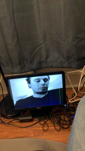
P.S. The extremely poor image quality here is due to the fact that I am photographing an extremely old VGA panel with my phone. The image looks far better in person and is free of the defects seen in this image (the blue line is from the panel being damaged, and the image distortion is from me having to “pause” the FPGA by unplugging the camera’s power so that I can use my phone to photograph).
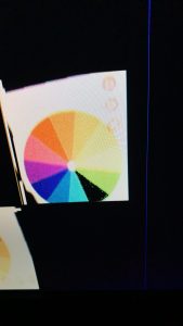
An example of the chroma-key filter in action. The black slice of the color-wheel is a vivid green which the FGPA was configured to remove. As demonstrated here, the filter removes essentially all of the target color while not touching the nearby colors (lime and teal).
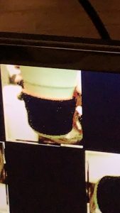
Here, I tested the image removal on a real-world object with texture. The grip on this coffee cup is a vivid red with lots of shadows and ridges that we anticipated making removal hard. Despite this challenging real-world test, Grace’s threshold feature built into her filter was able to detect even the off-red shadows as part of the “intended removal color” and handled it extremely well, removing essentially all of the grip as shown here.
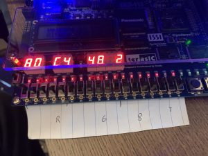
This is a photo of the barebones user interface I constructed to enable real-time configuration of the chroma key settings. Of the 18 hardware switches, we are using 5 for red and blue, 6 for green, and 2 for threshold (matching 565 color and allowing 4 levels of threshold removal). The current settings are displayed on the HEX outputs in RR GG BB T format, and the rightmost button temporarily changes the display to flash the currently set color for easy comparison to the background. The button just to the right of that bypasses the chroma-key filter to allow for a “before and after” comparison to ensure the filter isn’t removing anything desirable.
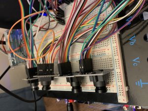
Here is a photo of all four cameras connected and functioning with our FPGA. All four of them work as intended and output independently to the screen as desired for our final product.

Breyden Wood’s Status Report for 4-10-21

This week, we were able to finish up all the work we were planning for the interim demo and are near to the “MVP” we defined for our project. I was able to take one camera and feed it into all four memory banks (which I created this week) at a resolution of 240p per camera with a total output resolution of 720p (this is the final memory hierarchy are planning to use for our project). From there, I was able to finalize the white balance of the camera and integrate the entire setup into the studio we constructed. This was combined with the TV and the pyramid into a fully functional studio-to-FPGA-to-display pipeline which we used to display some sample objects for our interim demo. This integration went smoothly and we were able to capture footage for our demo video of our complete pipeline. Our progress is on schedule, as all we have left to do is connect the other four cameras (all the FPGA design is set up for this, they are just not physically plugged in) and add the background removal filter for our final project. This next week I hope to continue working on adding the other cameras to the FPGA and working out some kinks in the autoexposure settings of the cameras, as it was a bit unpredictable in the filming of our demo video. My progress this week can be seen in the demo video of the project.

Breyden Wood’s Status Report for 4-3-21

This week, I have made significant progress with the camera and was able to resolve the significant issues with the color we have been seeing for the past week and a half. This task was made significantly easier with the aid of the oscilloscope we were able to borrow from the ECE labs, and the three major bugs we had would have been extremely difficult to detect without the scope. The first bug found was with the voltage of the logic the camera outputs. After scoping the data lines, it was found that the camera outputs voltages around ~2.6V for signals that are “high” with a significant ripple in the voltage of around +/- 0.1V. Our FPGA was doing GPIO logic at 2.5V, which meant that, with these ripples, the voltage for a logical “1” was occasionally dropping below 2.5V. This would cause the FPGA to occasionally read a negedge or a “0”, which was creating both visible static in the data of the image and occasionally distorting the entire image altogether when the clocking signal from the camera had false negedges. This was resolved by lowering the FPGA’s IO logic voltage. The next issue was with the timing of reading the data. Lots of documentation online suggested we read data values in at the negedge of the pixel clock, however, the rise time of the clock and data signals were such that reading at the negedge of the clock would result in incorrect data, leading to further distortion in the image. This was easily resolved by changing the logic to read at the posedge, which further reduced static in the image.

Lastly, the biggest bug we had was an extremely subtle bug in our I2C timing for programming the camera’s settings from our Arduino. We noticed that the bit pattern the camera was outputting didn’t seem to match the camera settings we applied from the Arduino. Furthermore, while some of the camera settings seemed to change things in the image, some of them didn’t. After much investigation, the oscilloscope revealed that the Arduino code we had been using to program the camera the entire time had been operating at a frequency of ~475KHz, slightly above the 400KHz maximum specified by the OV7670’s manual. We redid the Arduino code to communicate at a lower frequency and that change allowed us to correctly set the bit pattern, white balance, and other camera settings with the expected resultant effects.

In summary, we now have color input and output from the camera to the FPGA to the VGA display, which is a significant part of our MVP. I am now back on track for the interim demo and expect to spend most of this upcoming week working with Jullia to finalize the image combiner and redoing the memory interface to match our final specifications.


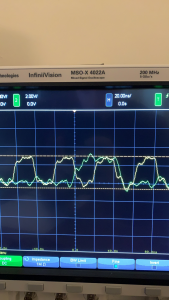
This image shows the timing and variance in the voltages. The clock line is in yellow and one of the data lines is in green.

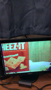
This image shows the working color output of the camera. The colors are slightly off (mainly in deep blues and greens) due to the white balance not being fine-tuned. This has since been rectified in the lighting of my room, however.

Breyden Wood’s Status Report for 3-27-21

For this week, I have spent the bulk of my time working on getting camera input from the camera through the FPGA to the display. I did this by first wiring up the camera to an Arduino to test that it works, then wiring it through the FPGA and interfacing it with my existing VGA driver. Interfacing between the FPGA and the camera has proven to be more challenging than we initially thought, however, we have been able to successfully read in greyscale images (still working on RGB color) and output them to the display through a small framebuffer I created (160x480x24) for testing purposes. Through this process, I have learned how to control the internal registers of the OV7670 to change image and color settings, how to interface with and read this data into the FPGA, and how to create BRAM framebuffer modules. In terms of progress, we are on track as our goal was to have the camera interface done. For this upcoming week, I plan to figure out how to make the color work correctly from the camera as well as build larger buffers using the additional memory available on the chip.

Breyden Wood’s Status Report for 3-13-21

This week, we received our FPGA (DE2-115) along with our cameras (OV7670). I spent the majority of the week working on our first task as a team: implementing a PLL on our FPGA to generate the pixel clock for video output to the display. This required me to first set up Quartus and my development environment and also to research how to create PLLs for this specific board. Once I figured all of that out, I was able to implement our MVP output of 640×480@60Hz with a PLL-generated pixel clock of 25.175MHz and a test pattern VGA controller to generate the pixels themselves. Once this was done, Jullia and I wanted to demonstrate that we could extrapolate this design to different resolutions and clock frequencies (our camera needs a separate clock and our goal is 720p60Hz). We were able to prove this as possible by upping the resolution all the way to 1440×900@60Hz with a new PLL-generated clock of 106.47MHz. This was also successful (see photo below), and thus we have successfully mitigated the risks of our resolution being PLL limited. We are slightly ahead of schedule given that we have a sample VGA-controller implemented, and this upcoming week I plan to expand on this by experimenting with the cameras to verify compatibility and remove them as potential risks for the future.

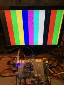
Our test pattern being outputted at 1440×900@60Hz over VGA from our FPGA using a PLL-generated clock of 106.47MHz. Please note that the two off-color blue and green thin vertical stripes on the right are due to defects in my (slightly damaged) panel and are not from our VGA signal.

Breyden Wood’s Status Report for 3-6-21

This week, I spent much of my time working on the design presentation with my teammates as well as extensively researching the parts that went into that presentation. Of this, I spent most of my time looking over two things: the FPGA pinouts and the camera’s specifications. As discussed by Jullia and in the team status report, we had a major issue with selecting our FPGA. If we used the board from 18-240, we had access to better PLLs, more Logic Elements, and more RAM, but only 40 GPIO pins. The boards from 18-341 had 80 GPIO pins but sacrificed in all other areas. Eventually, we were able to resolve this by looking into a daughter expansion board for the DE2-115 (18-240 board) that I found. The DE2-115 has an expansion slot on the side that can be connected to a number of devices, namely a GPIO expansion board that provides 3 additional GPIO bays. This board can be had relatively inexpensively (~$60, depending on retailer) and gives us all the GPIO pins we need to run our cameras.

Additionally, I also spent much time looking into the OV7670 specifications as that is the camera we decided to use. I searched extensively to find the FOV of the camera as that is required to calculate the size of our studio, however, all I was able to find was a vague reference to 25 degrees with no mention of diagonal, horizontal, or vertical (or vertical from the axis). I was able to find some test images, and judging from these and my photography background my best guess is the FOV is 25 degrees vertically from the horizontal axis. From this, I was able to estimate the size of our studio at around 8 inches by 8 inches, but this is subject to change if the camera’s FOV turns out to be significantly different.

Breyden Wood’s Status Report for 2-27-21

This week, I worked on several things. The first thing I did was help Grace prepare the group presentation given on Monday (2/22). We worked on and finalized the PowerPoint slides together as a group, and then individually reviewed a sample practice video that Grace put together of her running through the presentation. After the presentation was done, I focused my work back on researching specifics of our design, specifically the FPGA and how we were going to get video output working. Our current plan is to use the VGA output of an FPGA to display to a TV screen with an output resolution of 720p to maintain a sharp image at all times. However, we have two problems we have identified we may run into with this. The first is to do with the pixel clock. A 1280×720 image running at 60Hz requires a pixel clock of approximately 75MHz, which is high enough of a clock that we would likely need to implement PLLs to generate a faster clock to drive the display. Additionally, a single frame at 720p requires a 3MB frame buffer, which may exceed the amount of onboard memory available to us on the FPGA.

To resolve this, I have been researching fallback plans to increase visual quality in the event we have to settle for a lower resolution such as 480p. Our first plan to mitigate this is to have a robust sharpening filter, which is part of our current plan for one of the image filters inside the FPGA’s ISP. However, even with a strong sharpening filter, the outputted image would still be 480p. One way to get around this is to use a VGA to HDMI adapter, and then run the image through an HDMI upscaler. This has the benefit of shortening our VGA cable length (long cables can introduce noise into the analog signal), while dramatically boosting visual quality with the upscaler as many of these use advanced post-processing to increase quality along with resolution (versus simply stretching a 480p image to 720p or higher). One such product I have found is the Marseille mClassic (originally designed for boosting visual quality from game consoles), which reviews claim can take a 480p source to near-1080p quality (see photo below from the mClassic website).

Into next week, I plan to continue researching how we can get a high-resolution feed out of an FPGA and the potential of these fallback solutions, as well as selecting a specific board that we can begin development on. This mirrors our current work plan for this upcoming week (research), and will keep us on track for success in our project.


Breyden Wood’s Status Report for 2-20-21

This week, I put most of my effort into working on the presentation, specifically most of the image quality requirements and defining the metrics for latency and performance of the system. I have a strong background in digital photography, and I was able to provide that knowledge to the team by defining concrete metrics for how we can test and measure image quality and sharpness as we apply filters and set up the cameras. I also know a fair bit about displays and framerates, so I was able to apply my knowledge to defining requirements for frame stability and pacing. My progress is on schedule, as my group and I are nearly finished with our proposal and are preparing to present this upcoming week. This next week, I hope to help Grace give the presentation and begin ordering the materials so we can start construction of the HoloPyramid soon after.