These past two weeks I have (with the help of Grace and Jullia) wrapped up all the finishing touches on the FPGA and camera side of our project.
Firstly, I took Grace’s complete chroma key filter and integrated it into the memory-to-display pipeline. Her filter allows us to select any color value in 565 space and remove all pixels matching that value within a user-settable threshold. I integrated this filter into our pipeline along with all 18 hardware switches and LED displays so that the user can easily fine-tune the removed background color and how sensitive the filter should be. Furthermore, to aid in this tuning process, I added two buttons to work as a temporary filter-disable and a “display color to be removed” option. This allows the user to input a value in hex using the switches and LEDs and tweak it by comparing the removed color to the background color until the filter has the desired effect. In my testing, the filter works extremely well and can remove a variety of colors nearly completely (even in the adverse lighting conditions of my room). Sample photos of the filter and hardware-switch UI can be seen below, and we expect the results to be even better in a controlled lighting scenario such as the studio.
After completing this, I integrated the remaining three cameras to complete our four camera setup (one more on GPIO, two more on the HSMC expansion card). As predicted, this process was fairly straightforward and did not require too much time in Verilog outside of physically wiring the cameras into the board. A photo of this can be seen down below. I also took care of fixing a few image-quality issues that were pointed out to us in our demo feedback (a white bar on the top of the images, and some distortion near the bottom). These fixes were easy to implement (some minor memory errors), and are no longer present in our working product. Thus, essentially all of the FPGA work is done and our project is very near completion. All that remains now is to connect the cameras into the studio, tweak some of the Arduino settings to get an optimally sharp and clear image, and run our image quality tests that we identified earlier in the semester.
As part of the image-enhancing process, I will likely swap out the first connected camera we have been using for one of our spares sometime this week. As noted in the feedback for our demo, the image quality wasn’t the best (and we ran into plenty of issues with auto exposure and auto white balance off-camera). Now that all four cameras are connected, it is clear that the first camera is slightly defective and gives a significantly worse quality image than the other three. This may be due to either an issue in QC (one of the cameras I tested was dead on arrival), or it may be damaged from me accidentally shorting a few of its pins while probing with the oscilloscope a few weeks ago. I plan to quickly make this swap and complete the studio integration this upcoming week so that we are “good to go” for our final presentation and demo!
P.S. The extremely poor image quality here is due to the fact that I am photographing an extremely old VGA panel with my phone. The image looks far better in person and is free of the defects seen in this image (the blue line is from the panel being damaged, and the image distortion is from me having to “pause” the FPGA by unplugging the camera’s power so that I can use my phone to photograph).

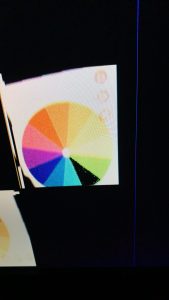
An example of the chroma-key filter in action. The black slice of the color-wheel is a vivid green which the FGPA was configured to remove. As demonstrated here, the filter removes essentially all of the target color while not touching the nearby colors (lime and teal).

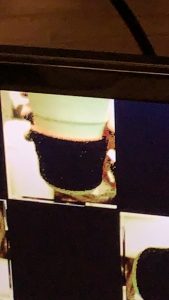
Here, I tested the image removal on a real-world object with texture. The grip on this coffee cup is a vivid red with lots of shadows and ridges that we anticipated making removal hard. Despite this challenging real-world test, Grace’s threshold feature built into her filter was able to detect even the off-red shadows as part of the “intended removal color” and handled it extremely well, removing essentially all of the grip as shown here.

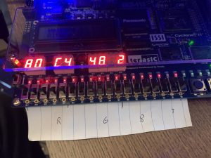
This is a photo of the barebones user interface I constructed to enable real-time configuration of the chroma key settings. Of the 18 hardware switches, we are using 5 for red and blue, 6 for green, and 2 for threshold (matching 565 color and allowing 4 levels of threshold removal). The current settings are displayed on the HEX outputs in RR GG BB T format, and the rightmost button temporarily changes the display to flash the currently set color for easy comparison to the background. The button just to the right of that bypasses the chroma-key filter to allow for a “before and after” comparison to ensure the filter isn’t removing anything desirable.

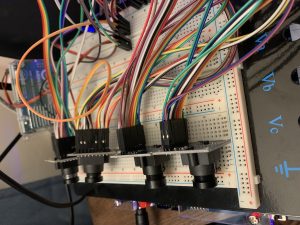
Here is a photo of all four cameras connected and functioning with our FPGA. All four of them work as intended and output independently to the screen as desired for our final product.
One thought on “Breyden Wood’s Status Report for 4-24-21”