This week, we just focused on the filming of our video and polishing the project as much as we could. I met with Vedant and Alvin in the lab, and we gathered a lot of footage of the project in action, in addition to collecting logs of all the ROS communications for future processing in simulation. We planned out the length of the video and how we would break down each component of the design. Finally, I recorded my segments at home.
Siddesh’s Status Report- 5/1/21
This week, I worked with the team in the final stages of integration. At the start of the week, I helped Alvin with the motion planner. I downloaded the Embotech Forces Pro license and software for the Jetson TX1 and tried to debug issues with the Forces Pro solver not respecting constraints and outputting motion plans with weird quirks (reluctance to move backwards or yaw beyond a certain angle). We tried to simplify the model, or switch to scipy.optimize.minimize, but the simplified models were very inaccurate and the minimize method took upwards of 17.5 seconds to solve a motion plan. Eventually, we decided to switch to the preliminary motion planner I had come up with two weeks ago, where we only changed the x and y position of the drone while keeping yaw and elevation fixed. This seemed to work well in simulation, and more importantly the drone’s motion was relatively stable, easing some of our concerns with safety.
I also worked on dealing with the local position issues with the rest of the team in lab. I collected local position data for a variety of test paths in order to understand how the drone’s position coordinates mapped to real world coordinates. I also helped in the camera calibration to try and debug issues in the conversion from pixel coordinates to real world distances. In the process of dealing with these issues, I helped the team reflash the drone’s flight controller with the Ardupilot firmware in efforts to make the position data more accurate by adding an optical flow camera. However, we eventually encountered issues with the GPS fix in Ardupilot and decided to switch back to Pixhawk.
The rest of the time spent with the team in lab basically involved debugging an assortment of miscellaneous issues arising with the flight controller, such as a loss of binding with the radio transmitter and a refusal to switch to auto mode mid-flight. Eventually, despite the turbulent weather, we got the drone airborne and hovering in place, but decided against running our full motion planning stack due to wild behavior of the drone. Instead, we focused our energies on getting as many metrics as we could from our actual setup (target precision and recall, video FPS, streaming latency), and getting the rest of the metrics from simulation.
Team Status Report- 5/1/21
This week we aimed to complete our integration and be able to run our full stack successfully on the drone. However, several issues presented themselves on our way to trying to complete this goal. Firstly, while we could issue positional commands to the drone in order to move to certain positions, we needed to understand how it’s own internal local position coordinates mapped to real world coordinates. After conducting tests moving the drone across different axes and sending the local position estimates through the Rpi to the TX1, we noticed some startling issues. Firstly, even while stationary, the positional estimates would constantly drift within +/- 3m in the x and y directions. Finally, the initial x, y and z estimates seemed to be completely random. The flight controller is supposed to initialize x, y, z to (0, 0, 0) at the location at which it turned on. However, each of these coordinates seemed to be initialized to anything between -2 and 2 meters.
We tried to combat these inaccuracies by downloading a different firmware for the drone’s flight controller. Our current Pixhawk firmware solely relied on GPS and IMU data to estimate local position. On the other hand, the Ardupilot firmware allowed us to configure an optical flow camera for more accurate local position estimate. The added benefit of this would be without a need for the GPS, we could even test the drone indoors. This was especially important since the weather this week was very rainy, and even when the skies were clear, there was a considerable amount of wind that could have been interfering with the position estimates. Unfortunately, there were many bugs with the Ardupilot firmware, namely that the GPS outputted a 3D fix error when arming despite the fact that we had disabled the requirement for GPS when arming. After troubleshooting this issue, we eventually decided to switch back to the Pixhawk firmware and see if we could fly despite the inaccurate position estimates. In doing so, the radio transmitter for manual override somehow lost binding with the drone’s flight controller, but we managed to address that issue.
In addition to the local position issues, the other major problem we needed to debug this week was our motion planner. The issue was the tradeoff between the speed and accuracy of the motion planner. Using scipy.optimize.minimize methods resulted in very accurate motion planning, but the motion planner would take upwards of 18 seconds to solve for a plan. Reducing the number of iterations and relaxing constraints, we could optimize this down to 3 seconds (with much more inaccurate plans). However, this was still too much of a lag to accurate follow an object. Another approach we took was acquiring a license for Embotech Forces Pro, a cutting edge solver library that is advertised for speed. While Forces Pro would solve for a motion plan in less than 0.15 seconds using the same constraints and optimization function, its results were less than ideal. For some reason, the solver’s results had a reluctance to move backwards and yaw beyond +/- 40 degrees. Eventually, however, we were able to create a reliable motion planner by reducing the complexity of the problem and reverting back to a simple model we made a couple weeks back. This model kept the yaw and elevation of the drone fixed, only changing the x and y position. The results of this motion planning and full tests of our drone in simulation can be found in the “recorded data” folder in our Google Drive folder.
Unfortunately, despite the success in motion planning, and finalizing a working solution in simulation, we were not able to execute the same solution on the actual drone. We tried pressing forward despite the inaccuracies in local position, but noticed some safety concerns. One simple test we used was we manually guided the drone to cruising altitude. Then, we switched off manual control and sent the drone a signal to hold pose. However, rather than holding the pose, the drone would wildly swing around in a circle. This is because due to the local position drifting while the drone was standing still, it would think that it was moving and try to overcompensate to get back. Because of this, we landed the drone out of concern for safety and decided to use simulation data to measure our tracking accuracy. However, in terms of measuring target detection precision and recall, we used data collected from the drone’s camera as we were manually controlling it.
Siddesh’s Status Report- 4/24/2021
(This status report covers the last two weeks since no reports were due last week).
At the start of two weeks ago, we all met in the lab but were struggling to get the drone flying and our camera image was entirely red tinted. Apparently, the auto white balance on the camera was completely screwed up. I created a main Python function on the Jetson that would automatically receive the images streamed by the Raspberry Pi, run the object detection and display the results on the monitor screen. I modified the main function so we could manually send white balance values to the Raspberry Pi and have it change these values for the camera on the fly so we could adjust the white balance of the photos. Still, the image was extremely desaturated no matter what we tried.
Eventually, we decided to get a new camera (and a Wi-Fi radio we could hook up to the drone to receive error messages while attempting to fly). While waiting, Alvin and I tackled drone motion planning- each one of us using a separate approach. The idea behind drone motion planning is that we already have a target detection algorithm and a target state estimator that can model the future movement of the target. We now need to model the future movement of the drone and create a motion plan such that:
- The target stays close to center of frame.
- The drone doesn’t have to make extreme movements
For my approach, I created a 3D simulator that simulated the target’s motion, the drone’s motion (based on our motion plan) and the drone camera output (based on the camera’s internal matrix). The simulator is pictured here:
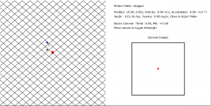
My approach to motion planning was to run optimization on an objective function, trying to minimize the following two quantities:
- The negative dot product between the unit vector of the camera orientation and the unit vector from drone to target. Basically, the higher the dot product, the closer the target is to center. Since this is a minimizer I took the negative dot product.
- A regularization term that aims to minimize the sum of the squared velocities in the drone’s motion plan (basically try and make the drone move as slowly as possible to accomplish our goals)
The relative proportions of these two can be tweaked. In our Google Drive folder, I’ve attached video of when we only try to minimize 1) and when we try to minimize both 1) and 2). The first case has more accurate tracking, but the drone’s movements are jerky and unrealistic. The second case has slightly less accurate tracking, but much smoother and achievable motion.
Finally, we received the new camera and Wi-Fi radio and began to set the groundwork for autonomous flight. First, we met in lab and actually got the drone to fly under manual control. We took test video, and to make things easier, I modified the main functions of the Jetson and the RPi so that the Jetson can send commands to the RPi that can handle events such as starting the camera or stopping the camera. I then modified the RPi’s config files so that the video streaming program would run at boot. This enabled us to easily start our video streaming. As soon as we connected the RPi to the drone’s battery it would start up the program headlessly, and then we could send it commands through the Jetson to start the video streaming.
After getting the drone to fly manually, I helped setup mavros on the RPi so we could connect via serial and finally start sending autonomous commands to the drone. Today, we were finally able to start sending basic autonomous commands to the drone and have it hover to a set position and remain there.
Siddesh’s Status Report- 4/10/21
This week I worked with the team to help the drone get up in the air in the lab. Unfortunately, we ran into a few setbacks during the process that we had to overcome. The first hurdle was that the Raspberry Pi 4 unexpectedly stopped working and gave us the “green light of death” where the green light consistently remained on rather than blinking as it was supposed to, and the Pi wouldn’t boot. I researched the issue, and there were a number of possible causes such as the SD card reader being faulty or a fuse tripping (which would take a few days to reset). I contacted various professors and organization, and eventually we were able to secure a replacement one from the RoboClub.
In addition, I worked with Alvin to get build the proper firmware to upload to the PixHawk flight controller in order to interface with the sensors, and to connect all the sensors together to the flight controller. There were again a few setbacks here, as the internal flight controller’s flash memory was too small to handle the firmware, and we had to constantly adjust the build ourselves and try and get rid of certain firmware features that we didn’t need in order to get the build to the right size. After a long while of tweaking, we were successfully able to upload the firmware successfully to the Pixhawk and setup the proper sensors and airframe.
I also worked with the group to try and test out how we would power the Raspberry Pi by using the LiPo battery on the drone as a power supply and sending it through a buck converter to regulate the voltage sent to the Pi. In addition, I helped with the testing of the camera to get a script that can automatically record video to an external flash drive, and successfully debugged an issue we had where when running the script from boot, the script would run before the OS had detected the external flash drive, leading to an error where the file location would not exist.
Tomorrow, we aim to get our drone flying successfully, as all the infrastructure for integration is finally in place. We plan on working on getting everything prepared for our demo, and going for our first test flights.
Team Status Report- 4/3/21
This week we focused on getting everything in perfect order before integration. First, we assembled the drone’s sensors and camera onto the adjustable mount and adjusted the hardware and tolerances until everything fit properly, the wires could connect safely and the sensors and proper line of sight.
Then, we focused on other miscellaneous tasks in preparation for full integration. We got the camera configured and working with the new RPi4, and started prototyping the circuitry for the passives for button control. In addition, we worked on the calibration of the camera in simulation (and measuring the actual position/pose of the real thing from our CAD design). Using this, we were able to perfect the transformation from 2D pixel coordinates to 3D coordinates in simulation and integrate the state estimator into the simulation. The successful integration of the state estimator into the simulation signaled that our drone tracking pipeline was finally complete.
Finally, we worked to start calibrating the LIDAR and optical flow sensor for drone flight. For next week, we plan to get the drone up in the air and perform rudimentary tracking. In preparation for this, we plan to write the ROS scripts to successfully communicate between the RPi and the TX1, fully calibrate the drone’s sensors and implement the button control to start and stop the main tracking program on the TX1.
Siddesh’s Status Report- 4/3/2021
This week I worked on the assembly of the drone apparatus, the calibration of the sensors and the integration of the state estimator into the simulator.
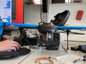
First, I went into the lab with the group to gather hardware and assemble the sensors and camera onto the configurable mount we 3D-printed. I finished mounting all the sensors and the Raspberry Pi, tested the tolerances, and ensured we had enough space for all the wires and the ribbon cable. Here is a picture below:
I also modified the CAD design to include the entirety of the IRIS drone rather than just the bottom shell. This is important because in order to convert the 2D image coordinates to absolute 3D coordinates, we need to know the exact position and pose of the camera relative to the internal Pixhawk 3 flight controller. Thus, I also added a CAD model of the flight controller to the assembly in the correct position so we could properly measure the position and pose in order to calibrate the drone’s sensors. This final 3D assembly can be found as “Mount Assembly 2” in the Drone CAD subfolder of the shared team folder.
Finally, I worked with Alvin to integrate the state estimator into the simulator. First, I had to modify the state estimator to work with 3D absolute coordinates rather than 2D pixel coordinates relative to the position of the drone. In order to do this, I added a z position, velocity and acceleration to the internal state model and modified the transformation matrices accordingly to account for this change. I then debugged the estimator with Alvin as we integrated it into the simulator in order to track the simulated red cube across a variety of different motions. A demonstration of this can be found in kf_performance.mp4 in the share folder. The target red cube’s position is marked by the thin set of axes. It accelerates and decelerates in extreme bursts to simulate a worst case (physically impossible) target motion. The noisy measurements captured by the camera and target detection are modeled by the small, thicker set of axes. Finally, the smoothed out motion from the state estimator’s motion plan is modeled by the larger, thicker set of axes. While the motion plan drifts slightly when the target accelerates rapidly, it does a successful job of smoothing out the extremely abrupt motion of this cube.
For next week, I plan to work with the team to get the drone fully into flight. I plan to help Vedant write the scripts for ROS communication between the RPi and the TX1 and finish calibrating the drone’s internal flight sensors with Alvin.
Siddesh’s Status Report- 3/27/2021
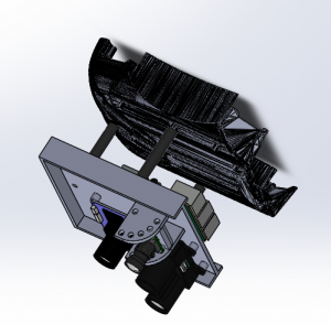
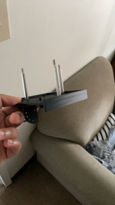
For these weeks, I first started the CAD design process for the drone mounts. I had to design a mount which could be attached to the underside of the drone and house the Raspberry Pi, sensors for the drone (a LIDAR and a PX4Flow camera) and our camera for taking video. The camera position had to be adjustable so that we could modify the angle between test flights and figure out which is optimal. In addition, I had to make sure there was enough clearance for each of the ports on the sensors / Pi and that there was ample room for the wires connecting them. The .stl files are in the shared folder. Here is a picture of a mockup assembly of the mount attached to the underside of the drone:
After asserting the design seemed to work in the assembly, I scheduled the parts to be printed (along with a few other drone guards we found online). The parts were successfully printed and I started the assembly:

In addition to this, I modified the state estimation algorithm to handle asynchronous datapoints. Rather than assume that updates to the drone’s state and the target’s detected position come together at a set fps, I modified the algorithm to handle asynchronous updates that are tagged with the timestep they were sent out. Since the algorithm requires the drone and target updates simultaneously, when one is received without the other, I predicted what the state of the other would be given its last known state and the delta t. Using this, the algorithm then updates its model of the target’s/drone’s movement.
Finally, I also helped Vedant try and get the camera working with the Raspberry Pi 3. We figured out that the kernel version of the Raspberry Pi 3 did not support the IMX477 camera and even though we tried an experimental way to update the 3’s kernel, we eventually decided we needed to get a Raspberry Pi 4 instead since this experimental update caused the 3 to stop booting.
For next week, I intend to start integration with the team. We will finish assembling the drone mount and I will help create the main function on the TX1 that integrates my state estimator and Vedant’s target detection. After this, we will test the communication between the TX1 and RPi and hopefully try a few test flights.
Siddesh’s Status Report- 3/13/21
This week I first sent test videos to Vedant for him to test out his target identification from a roughly 20′ elevation and under a variety of lighting conditions / target motion patterns. I then spent my full effort working on target state estimation. The purpose of target state estimation is to be able to model the target’s current motion at predict their future path. We can’t just identify the center of our target every frame and tell the drone “go to this position”. For one, the computer vision is not guaranteed to be perfect, and the center may not be exactly at the target’s center. Being “reactive” like this would likely create very jerky motion. More importantly, the drone’s flight controller needs to plan out movement at least a second or more into the future, so it would be impossible to simply receive a frame of data and react instantaneously. Thus, the goal is to smooth out the frame-by-frame target data outputted by the CV algorithm and create a model for the user’s current motion that would enable us to predict their motion at least a short while into the future.
In order to do this, I had to first create a test environment where I could generate a “random motion” and simulate the input that would be provided to the state estimator. To do this, I generated a random polynomial to model the target’s x and y coordinates as a function of time. Then, at a specified fps, I would sample the target’s current coordinators and add some Gaussian noise to mimic inaccuracies in the target detection before sending these samples to the state estimator.
For the state estimator, I implemented a Kalman filter from scratch where at each point in time we model 6 things: the target’s x/y position, x/y velocity and x/y acceleration. Every time the estimator receives a new “sample”, it probabilistically updates these 6 quantities within current model of the target’s motion. I then simulated how a drone would move based on the x/y velocities of the estimator’s modeled motion. For some reason, I can’t upload .mp4 files to WordPress but an example of this simulation can be found in StateEstimation1.mp4 in the Google Drive folder. (the black points are the target’s actual motion, the red points are the noisy samples that are sent to the estimator and the green points are how the drone would move based on the estimator output).
The Kalman filter approach seemed to be able to successfully smooth out the noise from the red points, and enable the drone to follow the target smoothly and relatively accurately. The next step was to simulate this with a more “human” motion rather than a contrived polynomial. The “human” motion has more gradual changes in acceleration and obeys a speed limit (10 mph). In addition to this, I let the target wander around infinitely and centered the screen to the drone position to get an idea of how a video feed coming from the drone would look. An example of this is in StateEstimation2.mp4
After tweaking the parameters, the results seemed very encouraging. The drone was able to follow a smooth motion plan despite the noisy data that was being inputted and the target generally stayed very close to the center of the frame in the simulation. For next week, I plan to make a minor change to the estimator in order to enable it to receive asynchronous samples (rather than at a fixed interval). In addition, I plan to test out the state estimator on Vedant’s results from target identification on the real-life video. Moreover, while I wasn’t able to design a mount to attach the camera and RPi to the drone (since the camera hadn’t shipped yet), I aim to get that finished next week.
Team Status Report- 3/6/21
This week, we started setting up the Jetson TX1. We tried setting up the TX1 and installing the SDK on a Windows laptop but this didn’t end up working due to using WSL instead of an actual Ubuntu OS. So, we met up at lab to download and configure Jetpack and install ROS on the Jetpack. During the process, we ran out of space on the internal memory. and had to research methods for copying over flash memory to an SD card and booting the Jetson from an external SD card. In addition. we started working on the color filtering and blob detection for identification of targets using a red Microsoft t-shirt as an identifier. In addition, we set up the drone flight controller and calibrated the sensors. Finally, we designed a case for the TX1 to be 3d-printed and worked on the design presentation.
For next week, we will continue working on the target identification, using test video we capture from a 2-story building to simulate aerial video from 20 feet up. In addition, we will start to work on preliminary target state estimation using handcrafted test data and design a part to mount the camera to the drone. We will also install the necessary communication APIs on the RPi and set up an initial software pipeline for the motion planning.