Team Status Update for March 28 2020

The primary risk to our project at the moment is the lag time associated with remote work. One team member’s already overslept and missed a morning meeting for discussing the ordering of one of the camera mount’s PCBs, and our Wednesday discussion this week was postponed by a substantial amount of time to accommodate the same team member’s breakfast. Even as I finish up this status report (barely an hour before it is due), one team member remains unresponsive to my messages even though a meeting was initially scheduled for 7 pm EST to do the report. This team member did not see fit to communicate a need to reschedule the meeting for a later time, or to keep the rest of the group up to date on their situation. The lack of punctuality (particularly in the case of morning meetings) is especially egregious in the context of one team member being in a time zone 3 hours behind the other two’s. This risk was originally managed by posting reminders of meeting times on the group chat, and explicitly confirming the times of future meetings before signing off from Zoom. However, since recent events have indicated that such measures are insufficient, I plan to collect phone numbers from team members and call missing group members at scheduled meeting times.

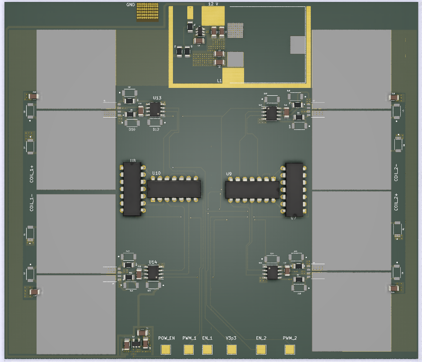
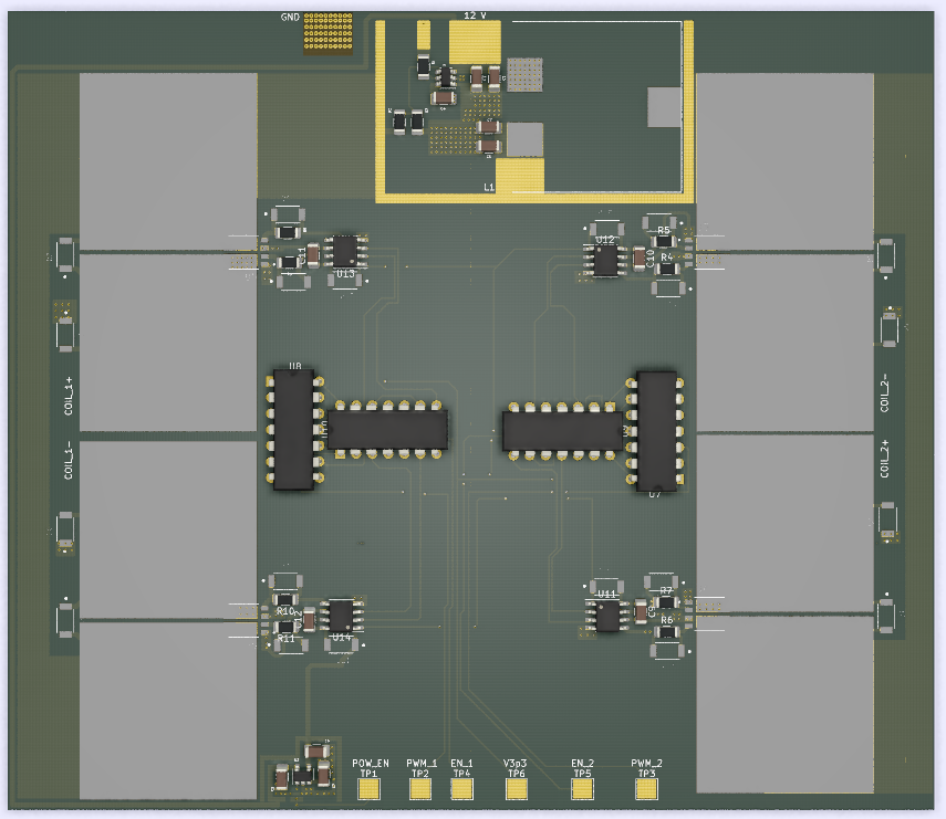
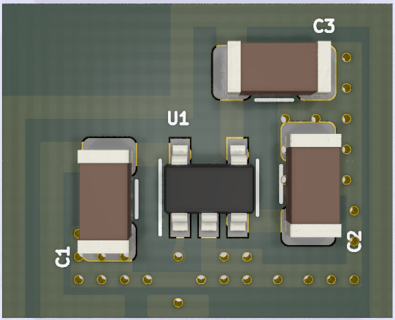
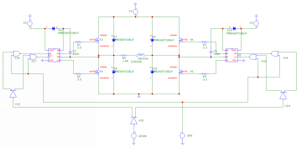
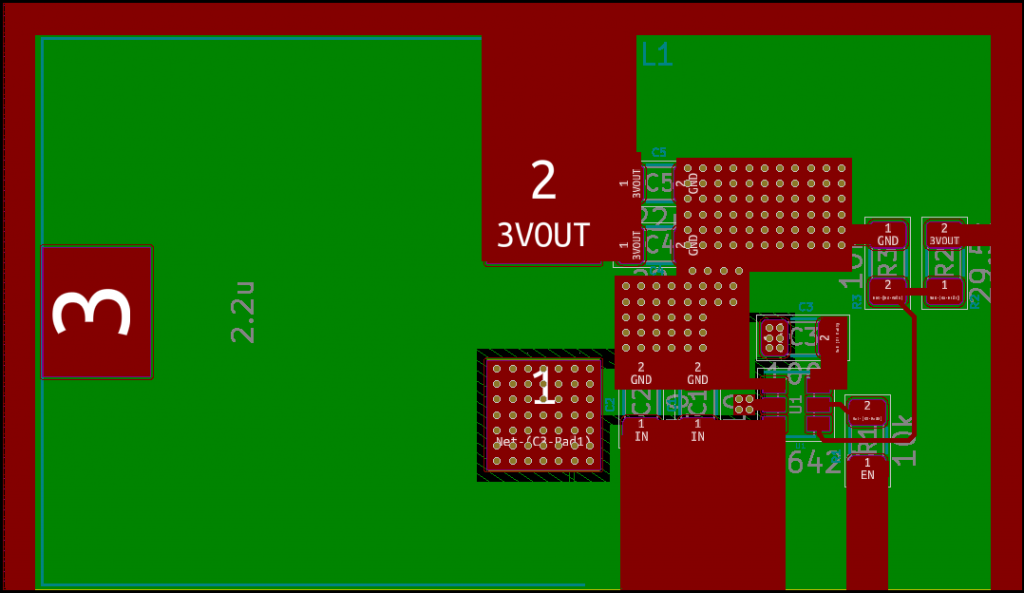
This week, the decision was made to change over to lower power unipolar stepper motors for driving the camera mount’s barn door compensator. This required the design and layout of an entirely new PCB for controlling said stepper motors and thus cost one of us a few days of time. This decision was justified by coronavirus-induced constraints on PCB fabrication, and the relatively lower torque requirements of a barn door compensator. The controller board associated with the original bipolar stepper motors was relatively large to accommodate the large currents needed for the motor windings, and would have needed to be fabricated by a Chinese manufacturer for us to remain in budget. Because the lower power unipolar stepper motors require less board area for heat sinking (and for the actual driver, since unipolar drivers are simpler than bipolar drivers), switching over to them allowed the affordable usage of a US-based PCB manufacturer that charged by the square inch and the avoidance of the undoubtedly long shipping times associated with overseas shipping at this time. Although the new unipolar stepper motors aren’t capable of providing as much torque as the original bipolar stepper motors, this is not an issue due to the lower torque requirements of a barn door compensator.

The updated Gantt chart for the remaining weeks of our project is as follows:

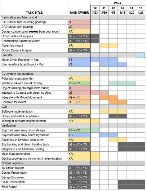
The majority of the assembly tasks have been delegated to Kenny, who has volunteered to integrate the mount components at his residence. Three tasks have been crossed out because of the change in the system design to a barn door tracker-based camera mount, and a task has been added for the investigation of Arduino-based alternatives for recording waveforms (since oscilloscopes are no longer available).

Updated Risk Management Plan:

Some notable risks for our project deal with failure to implement certain subsystems effectively or in a timely manner.

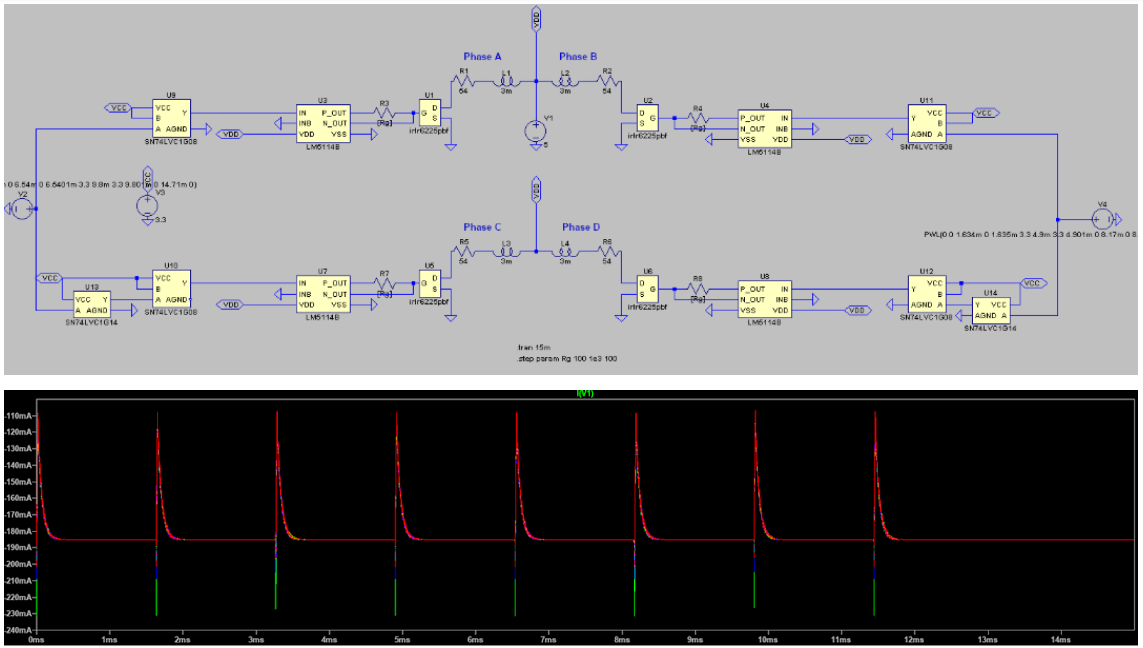
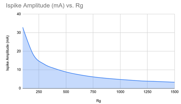
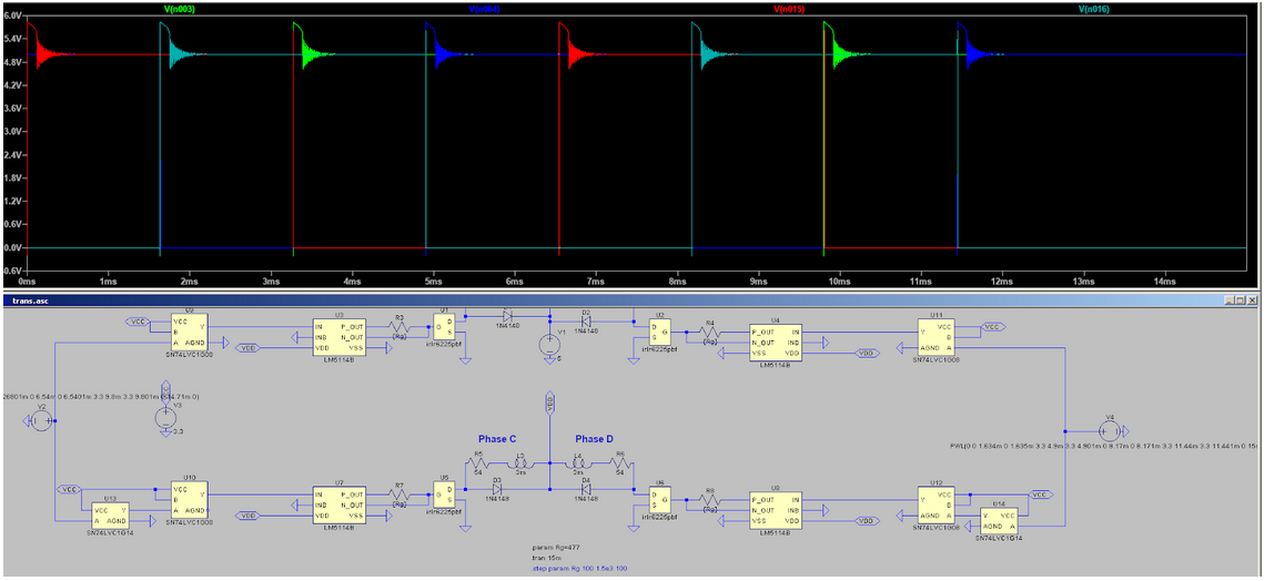
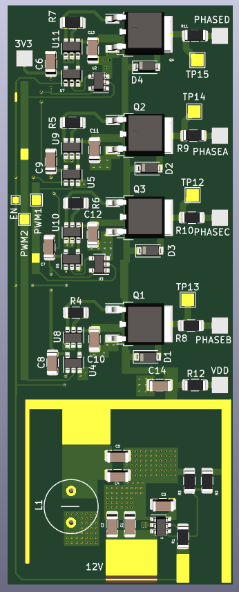
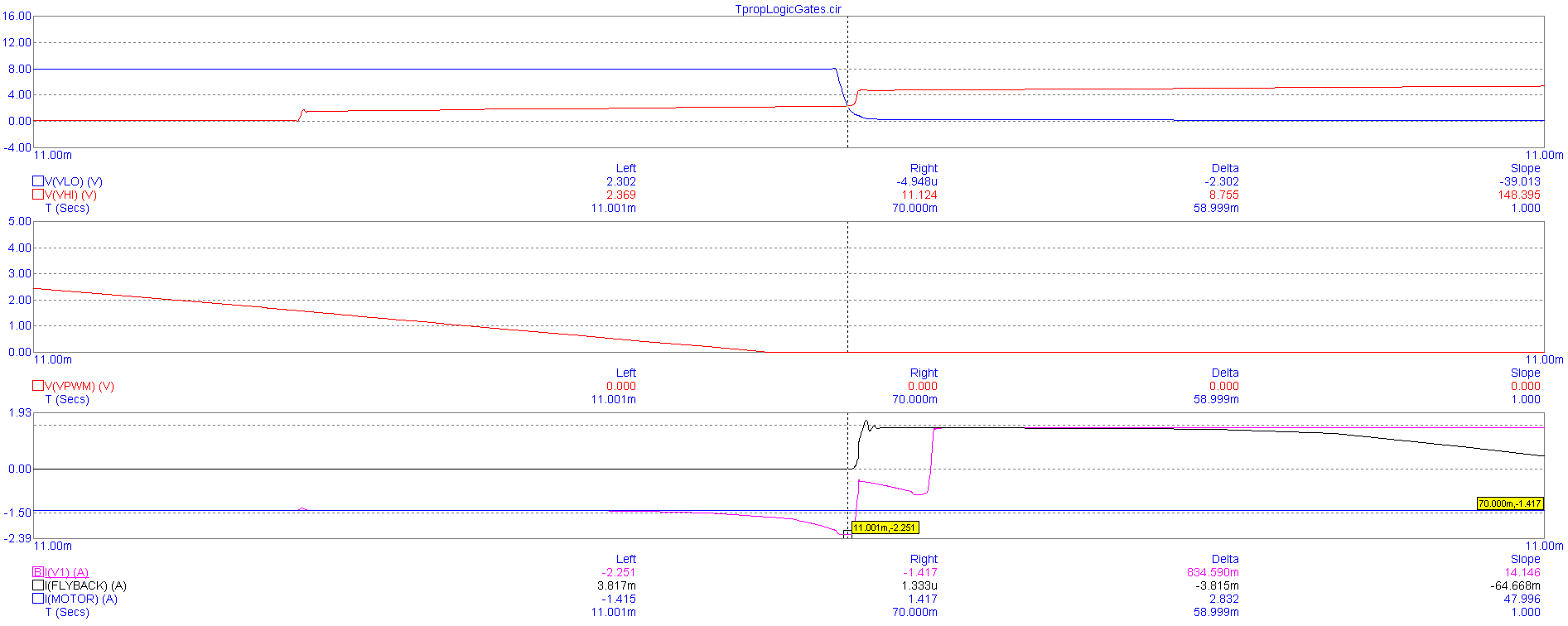
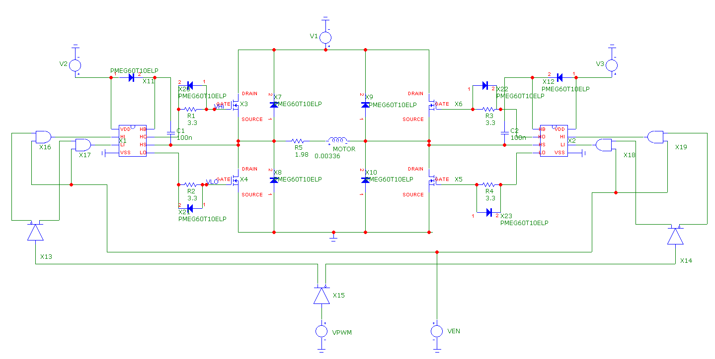
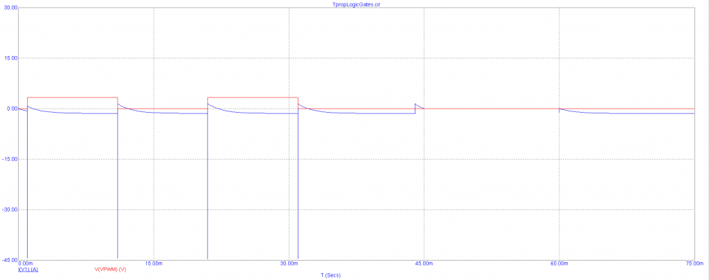
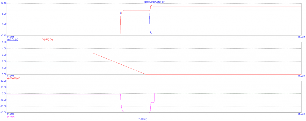
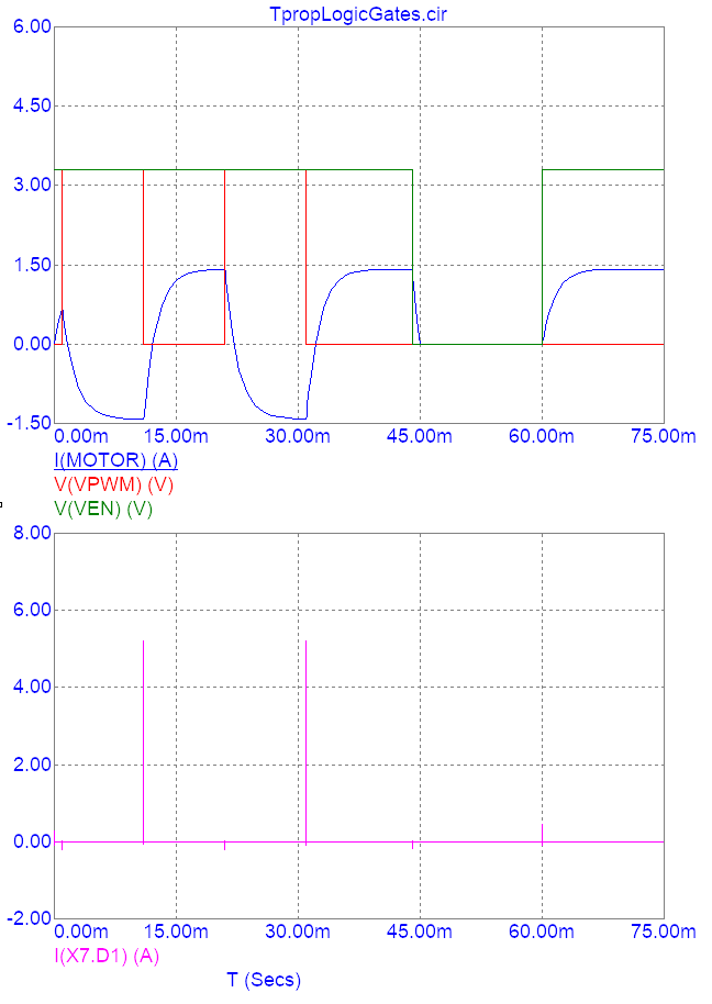
One risk we face is a failure to implement a working motor controller. This can happen due to several factors including stress and voltage spike test failures, and controller-driver interfacing errors. A solution for this subsystem failure would be to forgo implementing our own motor controller. Purchasing a driver controller module as a replacement would pose it’s own challenges as power distribution design would have to be altered to accommodate for the new module. We are also investigating means of debugging the motor controller upon arrival, in case there isn’t time to order a pre-packaged motor controller in the face of coronavirus-induced shipping delays. Thus far, this has taken the form of including means of monitoring the motor controller within the PCB (test points, current sensing resistors, etc.) and investigating the usage of an Arduino as a makeshift oscilloscope for interfacing to these means (now that an actual oscilloscope is no longer available).

In our original risk management plan, we mentioned a contingency for the failure of our project’s mechanical compensator in the form of a switch to a mechanically simple barn-door tracker-based compensator. Owing to the unavailability of CMU fabrication facilities and thus the inability to build our original design, this contingency has been implemented.

A third subsystem that could suffer failures is the computer vision software. If object-tracking is inaccurate, slow, or buggy, or if the latency of image transfer between the user-provided camera and the Raspberry Pi is too high to allow for real-time correction, real-time object-tracking will not be feasible. We can instead implement blind tracking based on known information about celestial objects or given input from the user. We could also repurpose the computer vision for drift alignment for polar alignment.

One major risk that has manifested in the move to remote work is the increased difficulty of debugging the software components of the project. The group member primarily responsible for our project’s computer vision routine is located in Pittsburgh, while the group member performing the integration of the mount’s hardware components is located in Miami, Florida. To alleviate the distance, we are investigating the possibility of setting up a ssh server on the camera mount’s Raspberry Pi so that remote debugging is possible for the person located in Pittsburgh. The principal challenge of this is making sure that the ssh server doesn’t compromise the security of the Miami-based group member’s network.

Fortunately, there are few new risks to the successful integration of the mount’s hardware. The team member in charge of physical assembly is familiar with both the mechanical and electrical sides of the project, and has assured the group that he is in possession of the equipment necessary to accomplish his tasks.

Regards,

Yuyi Shen

Yuyi Shen’s Status Update for March 28 2020

This week, I designed and laid out for a unipolar stepper controller board for the MIKROE-1530 stepper motor, which we’re switching to due to its lower power requirements. Although ready-made drivers do in fact exist for this stepper motor, the more common ones rely on BJTs to switch current through the motor windings, which have relatively high Vce,sat values. As a result, the decision was made to specify a controller board with low Rds,on MOSFETs (IRLR6225TRPBF) to bring the board’s power dissipation to a minimum.

Because of the relatively low complexity of unipolar motor drivers, the design process was fairly simple, with the exception of the selection of gate resistor values for the motor driver MOSFETs for limiting the degree to which the current waveforms through adjacent motor phases overlap. This overlap manifests as periodic spikes in the current from the power supply, and needs to be kept to a minimum to avoid overloading whichever module is supplying power to the motor. LtSpice simulation was performed with the below testbench to determine the impact of the gate resistor on the supply current spikes (graphed below):

The magnitude of the spike (measured using the steady-state supply current of 185 mA as a reference) was found to be inversely proportional to the gate resistor value:

Ultimately, a gate resistor value of 475 Ohms was selected to keep the supply current within 5% of the steady-state value. The logic gates for providing the motor controller’s ENABLE functionality and hardwiring the motor’s full-step sequence were included in the simulation to model the impact of their propagation delays on the supply current spikes. After this was finalized, high-speed 1N4148 diodes were added in shunt with the MOSFET body diodes to serve as flyback diodes and a transient simulation was performed to confirm that the voltages at the MOSFET drains did not rise beyond the 20V limit for the MOSFETs:

Because the current spikes through the flyback diodes do not exceed 92 mA in magnitude while the diodes themselves are rated for 2 A of surge current, this design is fine.

Unfortunately, due to a connection error during the layout, a revision had to be performed after the Google Form for the board order was submitted. The updated board order is linked here: https://oshpark.com/shared_projects/ezthQ1TM

The layout for the new motor controller board is shown here:

All IO pads on the board are surface mount, and so will require some skill from Kenny during assembly. Each logic input and the board outputs are equipped with either test points for debugging the board’s control inputs or current sensing resistors for measuring the board’s output current so that my SPICE simulations can be validated.

In addition to working on the motor controller for the mount, I also advised Kenny on the design of rudimentary constant-current drivers for the test setup’s laser diodes. To lower the strain on our budget and avoid the lead time associated with PCB fabrication, we chose to have Kenny solder together through-hole components in air for these drivers.

At present, I am on track with respect to our current schedule. Next week, I plan on going over the mount’s user interface with the others and designing a board based on their recommendations to serve as an electro-mechanical interface to the mount for the user. Thus far, we’ve been planning to use this interface board to permit the manual operation of the camera mount’s stepper motors and the selection of targets for object tracking.

Yuyi Shen’s Status Update for 03/21/2020

This week, I placed the finishing touches on the high power motor controller board. This mostly consisted of adding charge reservoir capacitors to decouple the H-bridges locally so that the voltage at the H-bridges won’t droop during operation. I also tidied up the PCB silkscreen so that the component designators are easily visible:

On JLPCB, the design should cost roughly $28.50, with an additional $17.55 for DHL shipping for 5 units. Thus far, shipping to the US with the aforementioned courier has not been impacted. With an estimated build time of 3 days, a shipping time of 4 business days, and a delay of 3 days (due to Coronavirus), we can get our designs done with a lead time of 10 days, which is still reasonable.

Due to changes in the scope of our project due to Coronavirus precautions, I’ve begun investigating the possibility of using a smaller 4096 step stepper motor (MIKROE-1530) for driving our project’s barn door compensator. This motor takes 5V (which would require a redesign of the primary SMPS), but only consumes 0.1 A per phase. Using IRLR6225TRPBF MOSFETs means that the static power consumption is less than a milliwatt, allowing the omission of area-intensive drain pads that would ordinarily be used for heat dissipation. The electrical complexity of the gate drivers also drops due to the motor being unipolar, allowing the usage of simple buffers (LM5114BMFX/S7003094) instead of proper half-bridge gate drivers like the LM5109B. Overall, changing over to this motor will allow the resultant motor controller board to be much smaller, giving us more headroom in the budget since the US-based PCB manufacturer we were planning to use as a backup in the case of further Coronavirus-based shipping restrictions charges by the square inch. Assuming that we fix a rotation rate of 1 RPM for this motor for the barn door compensator, the motor controller board will need to support 68 steps per second (which is well within the capabilities of an Arduino’s ADC to detect and record for debugging purposes).

Next week, I intend to consult with the faculty on the feasibility of performing the PCB fabrication through JLPCB in light of potential shipping restrictions. If it is possible, then I will perform a design review of the motor controller with Dr. Mukherjee and have the board ordered to Kenny’s location for assembly. As a contingency, I will proceed with the design and layout of a motor controller for the new 4096 step motor with the goal of keeping total PCB area below 4 square inches ($20 dollars on OSHpark).

Team Status Update for March 14 2020

Risk management:

The primary risk to our team’s success at present appears to be the changes caused by the recent pandemic. At present, we still don’t know what the plan is for capstone in the future now that CMU has switched over to remote instruction. This uncertainty has been rather demoralizing.

Since we’ll all be working remotely in the future, it’ll be far harder to collaborate on this project. As a contingency for team members falling behind, we can plan to have periodic Zoom meetings where we update one another, but this is no substitute for physically being present. There’s also the chance of one or more of us being infected, which is difficult to plan for. It’s hard to develop a contingency plan for the possibility of team members being unable to function effectively.

Assuming we are still designing the subject of our project, the main risk to the circuit design portion of the equatorial mount is the inaccuracy of circuit schematic simulation. It’s possible to take layout parasitics into account by placing estimated capacitances into the simulation window, but this isn’t a substitute for full-blown EM simulation. The main concern with respect to simulation inaccuracy is the shoot-through current spikes of the motor controller circuit. It’s been demonstrated in simulation that a specific value of gate resistor can control these spikes so that they don’t overly impact the circuit, but the existence of such things as gate inductances make the simulation output somewhat dubious. The contingency plan for mitigating such spikes at the moment is to simply place increasingly large gate resistors on the board, which has been shown to work in simulation.

As far as I know, no changes have been made to the existing system design.

Progress pic:

This week, the motor controller PCB was successfully laid out. The above is a 3D render of the resulting board.

Cheers,

Yuyi Shen

Note: Our team erroneously assumed that there was a status report due on March 7, and hadn’t realized we were meant to cover both weeks for this report. Therefore, please consult the following links for the remainder of the report:

March 7 Team report: http://course.ece.cmu.edu/~ece500/projects/s20-teamb1/2020/03/07/team-status-report-3-7-2020/

Kenny Ramos’s March 7 report: http://course.ece.cmu.edu/~ece500/projects/s20-teamb1/2020/03/07/kenny-ramoss-report-for-3-7-2020/

Joy Gu’s March 7 report: http://course.ece.cmu.edu/~ece500/projects/s20-teamb1/2020/03/07/joys-status-update-for-2020-03-07/

Yuyi Shen’s March 7 report: http://course.ece.cmu.edu/~ece500/projects/s20-teamb1/2020/03/07/yuyi-shens-status-update-for-march-7-2020/

Yuyi Shen’s Status Update for March 14 2020

This week, I resolved the shoot-through issues that the motor controller board was experiencing. This was mainly done by increasing the value of the H-bridge gate resistors until the MOSFET turn-on times were significantly longer than the turn-off times, generating dead-time in which neither MOSFET on a single side of an H-bridge is on. An acceptable shoot-through current spike specification was calculated by assuming that the shoot-through current was relatively constant for the duration of the spike (which was roughly 1 us in transient simulation), and relating the resultant flow of charge to a drop in the voltage of the H-bridge power supply output capacitors. By setting this maximal voltage drop to 0.03 V (so that the output capacitors retained 99% of the nominal output voltage after a shoot-through spike), I calculated that a maximum shoot-through current of 1.2 A for 1 us was satisfactory for the motor controller design. This maximum shoot-through current specification was found to correspond to a gate resistor value of 4152 Ohms in simulation. Setting the gate resistor to 4.22 kOhms (the nearest available value in Digikey) produced the following waveforms:

As can be seen from the pink waveform in the bottom-most plot, this value of gate resistor results in a shoot-through current spike of 2.251 A. From the waveforms of the hi-side and lo-side MOSFET gate voltages shown in the upper-most plot, we can see that the turn-on time (the red waveform) is much longer than the turn-off time (shown in the sharp edge of the blue waveform). Therefore, the circuit is operating properly for this value of gate-resistor.

Re-simulating for the circuit propagation delay, we find that the tplh of the PWM input is now 1.127 ms, while the tphl is 1.1 ms. Since this is much less than the period with which we plan to switch the motors, the gate resistors clearly do not overly impact circuit performance.

After making this refinement to the motor controller circuit, I generated a preliminary layout on PCB:

The 8V and 3V supply modules were pasted in from their respective layout files, while the remainder of the board was laid out in accordance with http://www.ti.com/lit/an/slva959a/slva959a.pdf. All that’s left is to place additional charge-storage capacitors at the power nodes. Here’s the updated schematic: schematic

I’m slightly behind schedule on this. I was supposed to complete the layout process earlier in the week, but ended up taking longer than expected. However, assuming that we follow the current schedule, all that’s left is to make the aforementioned revisions and perform a design review before ordering the board.

I’m uncertain as to what I should aim to complete next week. CMU’s recent move to remote instruction in light of the recent pandemic means that there will be substantial changes to the plan for capstone moving forward, and it’s unclear if there’ll still be a project component to this class.

Yuyi Shen’s Status Update for March 7 2020

This week, I worked on generating a preliminary layout for the motor controller board in KiCad. To accomplish this, I finished specifying and laying out an 8V LDO-based supply for the motor controller ICs:

It’s laid out in standard-cell format so that it can be easily dropped into the final motor controller board. We came up with an initial BOM for this supply for the design report, but I ended up revising it to better reflect the requirements stated in the voltage regulator’s datasheet: https://www.digikey.com/short/z8pr24. The revised BOM simply includes two large I/O capacitors, so there isn’t much of a change to the budget. The specific IC is the LK112M80TR (rated for 150 mA of output current). Fortunately, the low quiescent current draw of the motor driver ICs (22.8 mA in total for each controller board) means that we don’t need to include thermal considerations during layout design. It takes a 23.5 C temperature rise to produce a 1dB degradation of supply voltage rejection for this particular regulator (the key spec for a LDO), and it’s incredibly difficult to produce that with only 91 mW of quiescent power consumption.

I’ve also produced a PDF of the tentative full schematic for the motor controller: KiCad Schematic

At the moment, the layout of the motor controller board is being held up by the unwieldy footprints of the MOSFETs. Each MOSFET drain requires a 28 mm by 28 mm copper square to keep their temperatures below ~35 C during operation, resulting in this horrid thing:

It doesn’t help that the MOSFET drains are on one side of the package while the sources and gates are on the other, since drains and sources need to be connected in a H-bridge. I’ve gotten around this thus far by using one MOSFET in each IC (the ICs have 2 MOSFETs each) for individual half-bridges, but it requires excessive distance between the MOSFET gates and gate drivers (terrible for minimizing H-bridge ringing).

Luckily, there haven’t been any issues with copy-pasting the standard cells for the power supplies into the full motor controller KiCad project. I was initially worried when I figured out that it’s not possible to directly copy-paste between KiCad instances, but it turns out that EESchema allows users to append schematics, while the standalone version of PCBnew allows for appending layouts.

I’ve also run a new simulation of the H-bridge, with diodes placed at the MOSFET gates to speed up turn-off times and hopefully prevent shoot-through:

Unfortunately, simply placing the diodes there does little to prevent shoot-through, as can be seen in this simulation of the power supply current (the blue waveform) as the H-bridge is switched:

Clearly, there are immense current spikes exceeding 45A in amplitude as the motor controller PWM input is turned on and off. Simulating for the gate voltages of the hi and low-side MOSFETs on the “left” side of the H-bridge confirms that these spikes are caused by shoot-through:

The voltage at the MOSFET gates (the top set of waveforms) is high for both hi-side and lo-side MOSFETs for a short amount of time, causing the MOSFETs to short the supply to ground temporarily.

I’m behind by a week. I resolved to complete the motor controller board by the first half of this week, but was delayed by a series of unfortunate events (design report due on Monday, design review for another class, and an Open House event for prospective grad students). To catch up, I’ll need to resolve the shoot-through issues in simulation (hopefully through simply finding a circuit to copy-paste). Then, I’ll need to wrestle with the MOSFET footprints and find a way to position them so as to avoid adding extreme amounts of parasitic inductance into the gate driver traces. Lastly, I’ll need to talk with Kenny about what the circuitry for the test-setup should look like (so that he can do the actual design by himself, and perform sanity checks against our general expectations).

Next week, I hope to complete the layout for the motor controller board, and meet with one of the professors to perform a design review (probably in the latter half of the week). Given the challenges that this part of the project has posed thus far, I think that’s the most I can hope for.

Yuyi Shen’s Status Update for Feb. 29 2020

I estimate that I’m 1 week behind on the user interface board design and the layout for the motor controller board. I was also meant to start working on the test setup with Kenny, but he’s been bogged down with the mechanical portion of the project. This isn’t entirely unexpected, as I’ve been gone for almost half the week for a graduate student recruitment event. That, and course logistics have taken up a great deal of time (i.e. preparing for the design review presentation and the design report).

This week, I’ve only managed to setup my layout software with component symbols and footprints in preparation for laying out the motor driver board. Motor driver layout is precarious at best, so I’ve spent most of my time reading up on board design guidelines so that we don’t waste time re-spinning a board. I’ve also compiled a Digikey cart for the driver board: https://www.digikey.com/short/zq07q2 as a price estimate. Disregarding the cost of the PCB, the components for a single unit cost $18.91. This high price point is mainly due to the MOSFET gate drivers and H-bridge FETs, so it’s difficult to ameliorate.

To get back on track next week, I’ll first need to work with my team to get the design report done ASAP. Then, I’ll need to finalize the layout for the motor driver board and 8V power supply in the first half of next week so that we can send the orders out. In the remainder of the week, I’ll work with Kenny on the circuitry and layout for the equatorial mount’s test setup. The layout for the user interface board can be pushed back to Spring Break, since there hasn’t been much progress on the software component of the project.

Yuyi Shen’s Status Update for Feb. 22 2020

This week, I wrapped up the circuit design for the motor controller and did the layout for the motor power supply.

Since the majority of the motor controller circuit (up to the H-bridge gate driver ICs) had been simulated in LtSpice, what remained was the design of the chain of logic gates designed to reduce the 4 individual control inputs of the H-bridge gate driver chips to a single PWM pin with an ENABLE input. This was quickly accomplished by finding a logic buffer with delay-equalized complementary outputs (the CD4041UB chip) and a quadruple AND gate for implementing the ENABLE input (SN74HC08).

However, I was unable to simulate the full motor controller circuit until very recently, as the PSPICE model I found for the logic buffer was incompatible with LtSpice (the circuit simulator I had been using to work on the motor controller). Luckily, I found that the recently free Micro-cap simulator had functional models for both digital chips, and set up the following testbench for calculating the motor controller’s overall propagation delays:

Transient simulation with a handful of rising and falling edges at the PWM and ENABLE inputs produced the following plot:

Using the top set of waveforms, I determined that the PWM input’s rising propagation delay was 1.13 ms, while the falling propagation delay was 1.11 ms. Similarly, I found that the ENABLE input’s rising propagation delay was 1.12 ms, while the falling propagation delay was 0.41 ms. This did not change much when I conducted a worst case analysis with the simulation’s logic delay models. Since these values are consistent with the timing delays I had calculated in LtSpice without the logic gates, there is little reason to doubt the accuracy of the simulation.

Since these delays are insignificant in comparison to the periods with which the equatorial mount stepper motors will be actuated (0.3 sec), we will not have to take them into account when programming the equatorial mount.

Furthermore, I’ve confirmed that the flyback diodes I selected for absorbing voltage spikes at the H-bridge output are adequate. Judging from the lower graph, the most an individual diode will experience is a current spike up to ~5 A, which is substantially lower than the diodes’ non-repetitive peak forward current rating (35 A).

Lastly, I’ve finished laying out a PCB for the stepper motors’ 3V 4A power supplies:

The layout was performed in accordance with the guidelines that were laid out in the buck converter’s datasheet, and no major current-carrying trace has a width lower than 40 mils (the width required for 4A of current to cause a maximum of 10 degrees C of temperature rise with 2 oz. of air-exposed copper). The resulting “standard cell” can be dropped into a standalone instance of PCBnew (KiCad’s layout utility) for integration with the motor controller section. As can be seen, the 3V output is available on 3 sides of the cell for ease of placement in the future. Major current-carrying traces will be exposed to air instead of being covered by solder mask.

Unfortunately, I am behind on my schedule. I have yet to make progress with selecting a gyroscope, which I’ll need to finish up next week after consulting with Kenny on the required precision. Fortunately, this involves minimal circuit design, so catching up will be fairly simple.

Next week, I’ll need to design and layout a 8V buck converter for powering the motor controller ICs, in addition to laying out the actual motor controller in KiCad. This 8V buck converter will be laid out in the same manner as the 3V power supply shown above, although it will be easier to design due to the lower current requirement. Due to this, I do not plan to provide an ENABLE input for it in the layout.

The primary concern at this stage of the design is the layout of the motor controller H-bridges. If there is too much parasitic inductance, there is a possibility that the H-bridge MOSFETs will experience a shoot-through failure condition, destroying them. I plan on including diodes in shunt with the MOSFET gate resistors so that they turn on slower than they turn off (introducing a sort of dead time into the operation of the motor controller). If this fails, I can simply find a motor controller on Digikey that satisfies our requirement.