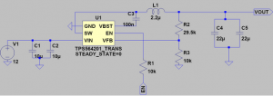
My tasks for this week were to finish designing the circuits for the equatorial mount’s stepper motor drivers and gyroscope. To this end, I have finished designing a buck converter circuit for supplying each stepper motor with 3V (and a maximum of 4A) from the 12 V supply voltage that we’re expecting:
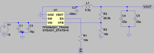
Furthermore, I’ve set up a bill of materials on Digikey for the design: https://www.digikey.com/short/z3w1wm. One assembly costs $8.22.
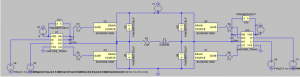
I have also specified appropriate components for the H-bridge circuits that will ultimately interface with the stepper motor coils:
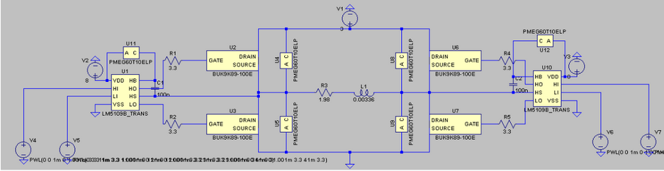
The MOSFETs were selected to have an on-resistance that’s 20 times less than the stepper motor’s worst-case series resistance spec so that they wouldn’t overly impact the current drawn from the motor power supply by the stepper motor coil. Similarly, the flyback diodes were chosen to have an on-resistance that’s on the order of the stepper motor coil’s series resistance so that they could effectively dissipate voltage spikes from the coil’s inductance. Lastly, the gate driver ICs were chosen to be compatible with 3.3V logic, as the Raspberry Pi has 3.3V GPIO pins.
To confirm my component selections, I ran LtSpice simulations to gauge the power dissipated by the flyback diodes if a single lo-side or hi-side MOSFET abruptly turned off (the worst case scenario in the context of kickback voltage transients). LtSpice simulation indicates that individual flyback diodes will dissipate a worst-case value of 754 uJ over 3.2 ms if a low side MOSFET suddenly fails open while passing current from the stepper motor coil. This corresponds to a power level of 0.24 W, which is about a third of the flyback diode’s maximum power dissipation. Therefore, the diodes that were selected will likely survive normal operation.
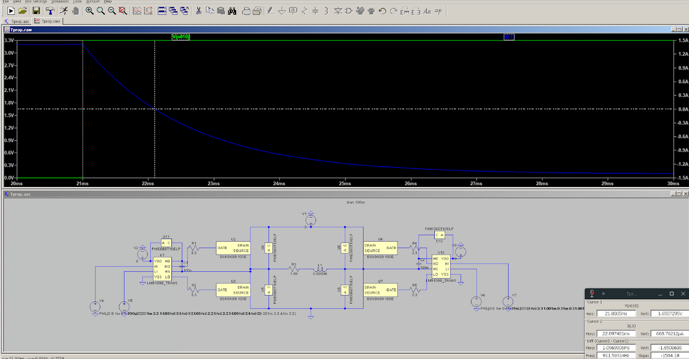
To facilitate my teammates’ work with the Raspberry Pi, I used LtSpice to characterize the propagation delay from the voltage at the hi-side input of one of the H-bridge’s gate driver ICs to the current passing through the stepper motor (modeled here as a series RL circuit). I found that the propagation delay for a falling edge at the hi-side input of a gate driver was roughly 1.08 ms, while the propagation delay for a rising edge at the hi-side gate driver input was 1.09 ms. This is very close to the theoretical propagation delay that can be calculated from the L/R ratio of the stepper motor coil (ln(2)*time constant), 1.2 ms. This means that the MOSFETs that I selected for the H-bridge will likely be effective at driving the equatorial mount’s stepper motors.
Unfortunately, I am behind schedule. To get back on track, I’ll need to find an appropriate gyroscope for the equatorial mount and design an interface circuit, and put the finishing touches on the stepper motor driver circuit. The former should be a fairly trivial task (most sensor datasheets will have a recommended circuit for facilitating the sensor’s interface), but the latter will consist of two significant tasks: designing an 8 V switched mode power supply for the H-bridge’s gate driver ICs and developing a chain of fast logic gates to convert the 4 H-bridge inputs into a pair of inputs (one enable input and one control input).
Next week, I intend to finish the stepper motor driver circuit. Given the time it took for me to simulate the fundamental H-bridge setup in LtSpice, I estimate that this will take at least half the week. Furthermore, since I’m scheduled to begin laying out the PCBs next week, I’ll aim to finish the layout for the 3V power supply that I designed this week for the motors.
The primary risk to this objective is the development of a logic chain for transforming the H-bridge inputs into a single control input for use with the Raspberry Pi that we plan to use for controlling the equatorial mount. Propagation delays for each of the 4 H-bridge inputs will need to be matched, which is a relatively difficult task to achieve. My contingency plan is to simply omit the logic chain altogether. This approach will use up more GPIO pins on the Pi, but is more likely to function.