The past few weeks I mainly worked with my team to fine tune the robot. As mentioned in the team status report, we improved the computer vision algorithm by fine tuning parameters for the edge detection code. Return towards the basket was also implemented. I also worked on the running tests for the final presentation. Currently my team and I are on schedule in delivering the final project. I would continue working on fine tuning the parameters, as well as on the final report and video
Ludi Cao’s Status Report for 11/20
This week our team worked together to integrate the subcomponents of the robot. First, we experimented with the MPU 6050 gyroscope but later realized that the IMU would have a better prediction. We also built the testing shelves for the robot. We then performed integration of moving to the basket, orienting with the shelf, driving up to the basket, recognizing a laser-pointed object, and retrieval of the object. There are still some issues with the computer vision laser-pointing technique as noise is still being picked up, but overall the project is promising. Hopefully, by Thanksgiving break, the laser pointer recognition can be improved, and a preliminary demo can be given.
Ludi Cao’s Status Report for 10/30
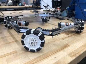
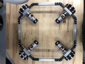
The robotics parts arrived earlier this week. I assembled the drivetrain chassis shown in the pictures below.


We are short on screw nuts, so I ordered more which should arrive in a day or two to add more securing between parts. I also tested speed control with the BTS7960 motor shield. I wrote the program such that the wheel speed changes based on the number inputted to the Serial monitor. Last week, I tested information passing between the Jetson Xavier and arduino through Serial.monitor as well and it worked. Hence, integration between the modules is promising.
Ludi Cao’s Status Report for 10/23
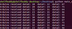
This week I worked on the software portion of the motor controller. I completed the initial setup for the Jetson Xavier, and installed the packages we would need for our project. Since the computer vision algorithms would be run on python, and the Arduino code is in C/C++, I wrote the communication channel between the Jetson Xavier and the Arduino.

The screenshot shows how the two entities communicate with each other when fed in some data. I also have written the logic of the drive train, specifically the omnidirectional logic for the different motors to move in different directions. I also briefly looked into the software code of adding encoders to our motors. Since the Intel Realsense cannot detect an object in a short distance frame, the drive train would need to travel a fixed distance after applying the computer vision detection from far away. Adding encoders would provide closed-loop feedback to ensure high accuracy. Since the hardware parts have not arrived yet, I am not able to tune any parameters of the skeleton code. Hence, the project is delayed behind schedule, but hopefully, the hardware parts would arrive early next week, and I am able to construct the robot and have an initial test of the motors and drive train accuracy.
Ludi Cao’s Status Report for 10/2
This week I finalized the main hardware structures for our robot. Esther and I agreed to use components from the Rev Robotics vendor. This is because the components are compatible, and we would not have to worry about booking inconsistent sizes or models from different suppliers. In addition, Rev Robotics has well-maintained documentation and CAD models for each part, which makes designing the chassis much more convenient. Since our robot would be 3 ft in height, I plan to design my chassis with roughly a size frame of 60cm x 60cm, along with 90mm diameter omni wheels. However, I haven’t done an extensive weight/force calculation yet to gauge the appropriate frame. I would invest in the details more throughout next week leading up to the design report, and this might likely change. Most of my progress this week has been prototyping / CADing the chassis frame. At first, I decided to use motors from other vendors, but realized that finding an adequate motor mount that fits other components in the Rev Robotics kit is very difficult. I also learned the importance of designing. While assembling the parts, I realized that the screw header from the motor mount would interfere with the wheels, due to the motor rod being too short for multiple components to fit on. This would be something I might not have thought of if I went straight into implementation, especially since these are the steps listed on the documentation. After choosing a new pair of mounts, and avoiding the usage of some pins, fortunately the issue is resolved.
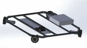
Attached is the CAD for the wheel chassis so far. I haven’t included some of the screws yet, but the overall design is not affected. I am using the Jetson Nano here in place of the Jetson Xavier since I couldn’t find CAD models for the latter, but since the overall dimensions for the two are the same, this is used for reference. The back of the robot represents a counterweight that helps balance the robot, since the claw would extrude forward to reach an object. I haven’t decided on what weights to use yet, and this would be determined through calculations of the force relationships, as well as experiments. I still need to include the motor drives, the H bridges, and the connections to the motors for this prototype to be finished, which I would continue to work on for next week. I would start ordering components next week, and research more on the quantitative analysis of our system design, especially the force/torque, and power requirements/limits. This result would lead to our design report. If I find time, I would start my research in the programming aspect of motor control, or start building the chassis if parts come in early enough and the design feedback is positive, where not much needs to be changed
. 
Ludi Cao’s Status Report for 09/25
This past week I did more research into the chassis design and motor requirements of the robot. I looked into the energy and cost tradeoff between various stepper / servo motors, and decided that the NEMA 17HS4401 bipolar stepper motors seem to be an efficient option. Given that our robot should not carry much weight (around 7-8 kg), the torque size of 40N should be sufficient as the motor accuracies should not be as important as computer vision detection and recognition. The proposal feedback mentioned the possibility of eliminating omnidirectional wheels in the design. The team still thinks that omnidirectional wheels in an easier option, since our robot has the horizontal movement of scanning through the shelf, as well as the vertical movement of reaching forward and backward to retrieve the item on the shelf. After some research, I found that most similar projects use two L298N motor drivers, where each connects to two motor drivers and is controlled by the Arduino board. Since the focus of our project is to accurately detect items on the shelf, I optimistically believe for now that if there is high latency between communication between the jetson nano and the Arduino, it would not be of great concern.
I am on schedule for this week. After discussion with my teammates about the research I did, I would order parts on Monday and start the CADing of the chassis. I would also begin to look into the battery requirements once the other significant components are finalized on our robot.
Ludi’s Status Report for 09/18
This week I discussed with team members on the feedback we received from the professor and TA. We worked on the presentation slides together, confirmed the division of labor, and wrote up the proposed schedule for designing and building the robot. I did some individual research on the hardware specifications and physical design of the wheelbase. I looked up relevant technical documents for the Jetson Nano board, Raspberry Pi board, Arduino boards, related electronics components, as well as the design report from past teams’ projects. I notice a potential issue of the wheelbase is that using omniwheels would be the most efficient way for the robot to move considering the vertical movement of reaching the object and the lateral movement of scanning through the items. However, only Arduino boards have enough PWM pins to connect to 2 motor drivers to control 4 wheels separately. There exist many successful robot projects with omniwheels controlled through an Arduino which is communicating with another computer board. I remain positive that the latency between a computer board and the Arduino would not be a significant issue. Since designing and building a wheel chassis is a relatively new experience to me, I also looked at various existing designs and posts on how to build wheel chassis from scratch.
For the next week, I would work on the CAD of the wheelbase, and order the physical components after the presentation. I hope to complete the majority of the design next week.
