The past few weeks I mainly worked with my team to fine tune the robot. As mentioned in the team status report, we improved the computer vision algorithm by fine tuning parameters for the edge detection code. Return towards the basket was also implemented. I also worked on the running tests for the final presentation. Currently my team and I are on schedule in delivering the final project. I would continue working on fine tuning the parameters, as well as on the final report and video
Team’s Status Report for 12/04
For the last two weeks our team worked together to integrate the various subsystems. Attached is a video which demonstrates that our robot can autonomously complete the majority of the work, including navigation to basket and shelf, identifying the pointed object with the laser tag, and successful physical retrieval of the item. In comparison to the last status report, the robot has much more consistent behavior, and most runs are nearly successful. Some solutions include adding an IMU sensor to the robot, so that the robot can orient itself after travelling some distance, to account for drift in the wheels. We experimented on finer tunings of the edge detection code, where the camera only looks at a specific area where the object is located at. This greatly helps in reducing background noise. We also implemented the last step of returning to the basket and dropping the item. Our team also ran some preliminary tests, as well as worked on the slides for the final presentation this last week. During this process we ran into the claw having inconsistent closing behavior, but after tweaking with the heights of the two sides, the performance is much better. Since the claw inconsistencies mostly come from the claw being worn down too much after multiple runs, we also ordered a new claw in case the claw malfunctions before the final demo.
We believe our team is on schedule, and the final delivery of the project is almost finished. Next week our group would mostly focus on the project report, final video, as well as last tweaking of parameters to achieve better consistency.
Ludi Cao’s Status Report for 11/20
This week our team worked together to integrate the subcomponents of the robot. First, we experimented with the MPU 6050 gyroscope but later realized that the IMU would have a better prediction. We also built the testing shelves for the robot. We then performed integration of moving to the basket, orienting with the shelf, driving up to the basket, recognizing a laser-pointed object, and retrieval of the object. There are still some issues with the computer vision laser-pointing technique as noise is still being picked up, but overall the project is promising. Hopefully, by Thanksgiving break, the laser pointer recognition can be improved, and a preliminary demo can be given.
Ludi Cao’s Status Report for 11/13
At the beginning of the week, I implemented the motor control code for the wheel chassis on the robot. The following video was performed during the interim demo.
After the demo, I worked with Esther and Bhumika to integrate our subsystems. I first experimented with the relationship between the motor spin time and the distance it would travel. The robot can accurately travel a specific small distance without much drift in all directions. Then, we incorporated the computer vision subsystem to work on various navigation sub-components. The robot can move towards an apriltag from an initial position at a tilted angle. The robot would first rotate to face parallel to the apriltag, center itself horizontally, and then move towards the apriltag, based on the location and angle coordinates of the camera. The other subsystem we worked together as a group is laser pointer recognition, centering the robot to the tagged object, and then moving forward towards the robot. Next week, we would add an IMU sensor for more precise movement of the robot in case of drift, and work on the remaining subcomponents: retrieving the item from the shelf and returning to the basket.
Ludi Cao’s Status Report for 11/6
This week I worked mainly on the navigation code and some design of the middle board which places objects. I implemented a program where the Jetson sends directions to the two Arduinos, and the motors spin accordingly based on omnidirectional rules. Attached is a video that demonstrates this behavior.
One promising thing I noticed is that, even though each motor is controlled by a separate motor driver, and the four motors interface with different Arduinos, the motors change direction at the same time. However, I do notice that there is a lag between the time the Jetson sends commands to the Arduinos, and when the motors respond to the command. Hence, this is something to be aware of when the Jetson sends information to the motors potentially about a frame captured slightly earlier.
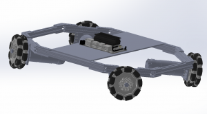
Esther and I also did a bit of designing of the board to place the various electronic parts. We think that we don’t necessarily have to mount everything on top of the board, but it is useful to create mounting holes for the motor shield, since there is a heat sink that gives it some height. We managed to measure out the dimensions for the motor shield. Attached is an image to show how the motor shield would be mounted. I would work on engraving the motor shields dimensions into the larger board, and hopefully have it laser cut on Monday or Wednesday.
To test how the robot currently navigates, I temporarily used a cardboard to place various electronics. Since I am testing in the lab room, I ran into the issue that the floor might have too little friction, resulting in the wheels spinning at different speeds. The robot would not go in the direction as intended. We plan to add a foam-like structure on the wheels to increase friction. I would also look further into my code and the mechanical structure of the robot to see if there’s anything to troubleshoot.
For next week, I plan to debug the issues about navigation ideally before the demo, laser cut the board to place the electronic components, and work with Bhumika to integrate computer vision into navigation. Hopefully, the robot can respond to camera data and move accordingly.
Team Status Report for 11/6
This week we finished the mechanical assembly of the robot, and are preparing for the interim demo for the following week. Bhumika has mainly worked on the computer vision area, with edge detection, laser detection, and april tag detection working decently well. The linear slides system is motorized and can successfully stretch up and down. The claw is experimented fully and can successfully grab objects within dimensions. The navigation code of the robot is under implementation. Currently, the four motors can receive commands from the Jetson Xavier and spin according to direction. We will continue to fine-tune our specific areas of focus and start working on integration later in the week.
Ludi Cao’s Status Report for 10/30
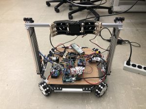
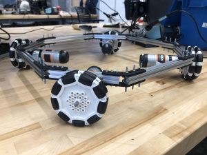
The robotics parts arrived earlier this week. I assembled the drivetrain chassis shown in the pictures below.
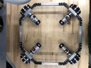
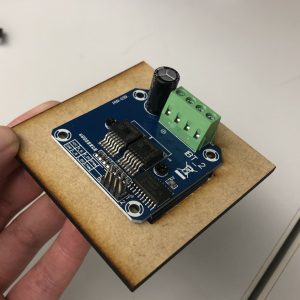
We are short on screw nuts, so I ordered more which should arrive in a day or two to add more securing between parts. I also tested speed control with the BTS7960 motor shield. I wrote the program such that the wheel speed changes based on the number inputted to the Serial monitor. Last week, I tested information passing between the Jetson Xavier and arduino through Serial.monitor as well and it worked. Hence, integration between the modules is promising.
Ludi Cao’s Status Report for 10/23
This week I worked on the software portion of the motor controller. I completed the initial setup for the Jetson Xavier, and installed the packages we would need for our project. Since the computer vision algorithms would be run on python, and the Arduino code is in C/C++, I wrote the communication channel between the Jetson Xavier and the Arduino.
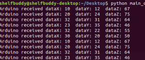
The screenshot shows how the two entities communicate with each other when fed in some data. I also have written the logic of the drive train, specifically the omnidirectional logic for the different motors to move in different directions. I also briefly looked into the software code of adding encoders to our motors. Since the Intel Realsense cannot detect an object in a short distance frame, the drive train would need to travel a fixed distance after applying the computer vision detection from far away. Adding encoders would provide closed-loop feedback to ensure high accuracy. Since the hardware parts have not arrived yet, I am not able to tune any parameters of the skeleton code. Hence, the project is delayed behind schedule, but hopefully, the hardware parts would arrive early next week, and I am able to construct the robot and have an initial test of the motors and drive train accuracy.
Ludi Cao’s Status Report for 10/9
At the beginning of the week I had an extensive discussion with my team to finalize the specific hardware we need to order and the associated bill of materials. We realize that budget is a concern, and based on that I slightly modified the base of the robot chassis to be smaller and more compact.
The base is now roughly 35cm * 35cm, where the straight extrusion on the sides are 20cm, and the diagonal extrusions connecting to the wheels are 12cm. Reverting to a smaller size would save up a log of cost material, and also make the linear shaft system steadier. Since the height of our robot is nearly 1 m high, and our claw system would stretch forward to reach an object of 1.5 lbs at max, I was initially concerned that the robot might “tip” forward when reaching out to a heavy object. However, based on the relative distances and weights of components, based on the lever rule in physics, the mass times distance towards the side of the robot is roughly 6 times as heavy than the same calculation done on the object side. Therefore, the need of a counterweight is also removed from my initial prototype of the robot.
I also did some other metrics calculations to confirm our system would meet our technical requirements. We aim to have the robot move at a speed of 0.5 m/s when not performing other computations. Based on our motor specs: 150 rpm and a wheel diameter of 90mm, according to the equations f = 2 pi f and v = rw, we derive that the ideal speed of our robot is 0.7065. Yet, our robot has a considerable weight, so taking a rough 20% deduction, our robot can still travel at a speed of 0.5625 m/s. Hence, I would anticipate our robot would just meet the requirements, and it would be interesting to experiment the results. I also calculated the power our system would consume, and find that our battery can last around 3.5 hours per charge where the robot is operating at full capcacity. This confirms that our robot is efficient enough to be used multiple times.
I am on schedule, although I didn’t find much time to explore the software side of the drivetrain, and we are a bit behind on ordering the materials. Next week our team would focus on the design report, and we would send the materials next Tuesday and hopefully have some parts delivered by then.
Team Report for 10/9
This week our team discussed and finalized the hardware components. We composed a bill of materials. With the Intel Realsense taking up almost half the budget cost, our current bill of materials would exceed the limit. We communicated this challenge with the professors, and appreciated greatly their understanding, as well as Tao’s kindness to lend his camera for us to experiment.
To satisfy the current draw requirements, we choose to use the BTS7960 DC Stepper Motor Drive https://www.amazon.com/BTS7960-Stepper-H-Bridge-Compatible-Raspberry/dp/B098X4SJR8/ref=sr_1_1?dchild=1&keywords=BTS7960%20DC&qid=1633569262&sr=8-1, since the motors draw an 8.5 A current at max. Different from the L298N spark fun motor drivers, only one motor can be connected to the motor driver instead of two. Hence, we would need six motors in total. We analyzed the pin layout of the Arduino and motor drivers, and realized that each motor driver would require 4 digital pins and 2 PWM pins that need to connect to the Arduino. Since each Arduino has 6 PWM pins as well as 14 digital pins, we would need at least 2 Arduino boards to connect to all of our components. Conveniently, the Jetson Xavier has 2 5V USB outputs, which can connect to 2 Arduino boards at max. We finalized our selection of the battery as well. Our design should meet the technical and physical requirements, and we are ready to compose our design report due next week.