This week my main focus has been bringing up the FPGA’s block ram functionality, as well as creating a reading and writing module for it to interface with the chorus effects module. Intially I went into this knowing about how much storage I would need in order to implement a chorus effect. Using that info I learn how to build a RAM module from the Quartus MegaFunction Wizard. That enabled me to setup the ram the way I wanted. In this case I determined that separate read and write ports on a 2 port RAM would be useful since the chorus effect works by delaying the input sound by various short intervals and recombining it with the original, which means I constantly needed to be writing to the memory as well as constantly reading from several places in memory. These behaviors are what my reading and writing modules are designed to do. They can vary depending on how many channels or ‘voices’ I want to have in my chorus effect as well as how much delay I’d like in the chorus voices. I will begin testing of the module onboard the FPGA next week as well as a doing more work to decode the MIDI protocol on our FPGA. My progress is slightly behind due to my busy job search, however I aim to get back on track as my interviews start to finish up.
Roshan Nair – Weekly Status Report #2
This week was continuing to come up with a concrete plan for how to structure the verilog code base.
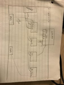
This was just a rough sketch done in lab, but through the discussion we organized all of the major modules required for the integration phase.
The panning module was written and I started testing and verifying the module. Based on a discussion with the rest of the team and Professor Nace we realized that having some sort of testbench that can use example wav files for the generated data and sending it through the DSP modules will be an efficient way of testing. At the same time we can ensure that our algorithms are correct from a auditory perspective by playing back these wav files and making sure that the sound played is the effect we expected.
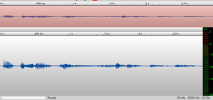
This is an example wav file that I have been using for testing purposes. I have written python code that allows us to read the data (stereo) by each audio frame. The plan is to then dump these values into some sort of systemverilog array file so that we can instantiate a driver to read and drive these values into our module for testing purposes.
Team A0 – Weekly Status Report #2
The greatest risks we currently have as team is the possiblity of our keyboard getting damaged which would be a significant hit to our budget, as well not being able to figure out the math behind some of our most complex effects which potentially involve Fourier transforms. We are managing these risks by using extreme care with out keyboard as well as working hard to set ourselves up to have plenty of time for working with the more complicated effects.
Our overall design has not changed significantly from our initial vision. This is because our initial planning for the system was robust enough that we had considered potential problems like memory for example.
Currently we are still on schedule. One thing we need to do is to purchase the speaker we intend to use for our project. This will be crucial when it comes to real world testing.
Nick Saizan – Weekly Status Report #2
This week my two goals were planning the chorus effect, and getting familiar with the MIDI output of the keyboard. For the chorus effect I had many things to consider. For example, I first needed to know how much memory I would need for an effect like this. So by taking our 44.1kHz sampling rate, 2-channel, 16 bits per channel audio, I was able to calculate that we’d need about 176kB of memory per second of audio we wanted to store. Based on qualitative tests in Audible where I tested various delays, I found that about 0.025s of delay between copies of an audio signal was where the effect started to sound unpleasant. So as a result I used this value to calculate that 4.410kB of storage was necessary for this effect. After discussion with the rest of the team we believe that using the onboard block ram of the fpga was the best solution, because we wanted to ensure our SRAM didn’t have other effects that might interrupt echoing’s performance. I’ve been looking into how to infer block ram in SystemVerilog code as well. My plan for the chorus effect is to constantly store the audio stream in my allocated block ram space, and then pull out copies at varying intervals from the stored data, depending on how much delay I want and how many “voices” I want in the effect. I also spent some time cleaning up our top level SystemVerilog module. This involved adding comments and headers for code readability as well as setting up a rough structure for how our effects will be integrated into and enabled within the top level module. The last thing I did this week was start to get a sense of how our MIDI keyboard is actually sending data, and begin to correlate that with the research I’ve done on the MIDI protocol. I’ve attached images of some of the signals I’ve seen. There is a MIDI start command and end command as well as some other data bytes related to the aftertouch capability. start status byte
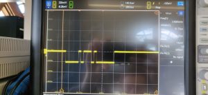 data byte
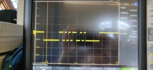 end status byte
This week we appear to be on schedule as the keyboard was shipped very quickly with amazon prime so I was able to begin testing already. Next week I hope to implement a MIDI decoder module in the fpga.
Nick Paiva – Weekly Status Report #2
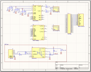
This week, I have worked on finalizing the PCB design. Since last week, I’ve added some extra components, double checked connections, and refined the layout. Here is the finalized schematic design: 
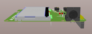
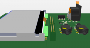
The final PCB is designed to slot into the GPIO connectors and replace the acrylic face plate on top of the FPGA. Here are renders from the top and side views respectively:

I have also completed a BOM for the PCB. For a single PCB, the BOM cost will be about $45. Here is a screenshot of the BOM:

Nick Paiva – Weekly Status Report #1
This week I worked on component selection and the PCB schematic design. As part of this I have worked on both schematic and layout symbols for all of the major parts. Now that I have most of the major symbols done, it will not take much longer to finish the schematic and get the PCB layout done.
In progress schematic:
3D CAD view:
For next week, I hope to have the PCB design finished.
Roshan Nair – Weekly Status Report #1
This week I helped in choosing MIDI keyboard for the BOM and continued working on bringup for the FPGA.
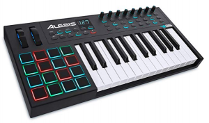
We finalized on choosing the MIDI keyboard here : https://www.amazon.com/Alesis-VI25-Controller-Assignable-Production/dp/B00IWVL3SW. This features both a MIDI output as well as the after touch keys and velocity sensitive pads.
Additionally I took last week’s SDRAM tests and started integrating/stripping it down so that we can use the controller independently from the rest of the Altera test files. This is still in progress.
I finished testing writes to the GPIO pins on the FPGA to make sure that we can properly observe the required voltage changes. Below are the results.
Tested using power supplied by laptop (usb)
- GPIO 0
- VCC5 = 4.632 V
- VCC3P3 = 3.327 V
- undriven pin = 0.53 – 0.61 V
- drive 0 to [34] = 0.205 mV
- drive 1 to [34] = 3.326 V
- drive 0 to [35] = 0.210 mV
- drive 1 to [35] = 3.326 V
- GPIO 1
- VCC5 = 4.633 V
- VCC3P3 = 3.327 V
- undriven pin = 1.0 – 1.1 V
- drive 0 to [3] = 0.288 mV
- drive 1 to [3] = 3.326 V
- drive 0 to [5] = 0.274 mV
- drive 1 to [5] = 3.326 V
For the next week I will begin researching more into the Panning effect as well as start writing a simple testbench so we can begin writing verilog for each of the DSP blocks.
Nick Saizan – Weekly Status Report #1
This week I was involved in planning for the PCB BOM and research into a couple of the effects we plan on using. For the BOM I first found the official MIDI documention which included some good schematic diagrams that will aid in our PCB design.
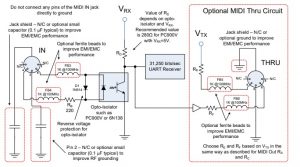
After I looked at this for a while I began adding some of the relevant components to our BOM, which included MIDI Cables, Optoisolators, Diodes, and Ferrite Beads.
Outside of this I did some research into information about the actual MIDI protocol and how to implement a Chorus Effect.
I found some good documentation from CMU about the MIDI protocol at this link: https://www.cs.cmu.edu/~music/cmsip/readings/MIDI%20tutorial%20for%20programmers.html .
I learned about the different elements to a MIDI message. One interesting point is that for messages that continue on the same pitch for a long time, they will often omit the STATUS byte and just send a stream of DATA bytes to be more efficient.
For Chorus I learned that there are actually several different elements that you might consider including in a chorus effect. For example sometimes these effects include some sort of pitch shift or amplitude modulation. However since these are effects are separate effects that we plan on implementing on their own I determined that for a chorus effect it would be best to simply use multiple copies of the signal shifted between 0 and 25ms and added together. This is based on some testing in Audacity where I played around with it to determine what sounded good.
Team A0 – Weekly Status Report #1
This week we’ve been working on laying the framework for our project. To get an MVP we have a few action items:
- Get the PCB designed, ordered, and assembled
- Verify audio circuitry
- Order MIDI controller and speaker
- Create basic design on the FPGA for simple effects
- Implement MIDI decoder
We hope to finish a few of those items this week.
The PCB and verilog code are being hosted on private github repos. In the verilog repo there is a docs directory which will act as a centralized point for all of our spec files and datasheets.
Individually, here is what we worked on last week:
Roshan has been working on testing the on board SDRAM and other synthesis tasks.
Nick S. has been researching the MIDI protocol and how to implement certain effects.
Nick P. has been working on the PCB/circuit implementation for the project.
Project Summary
ALTERAudio will serve as a compact, feature-rich replacement for effects pedals and and other similar devices which musicians currently use to modify their sounds live. Instead they can utilize their current MIDI controllers in conjuction with an ALTERAudio device to apply several, layered effects to their sound all at once with control over the characteristics of those effects. And best of all is that ALTERAudio’s list of supported effects is expandable since our hardware is re-programmable. With ALTERAudio we’re taking advantage of the underutilized information that comes with every MIDI key-press to make your performance more unique.