Author: npaiva
Nick Paiva – Weekly Status Update #11
This week I worked on frequency filtering, pitch shifting, and a sine function look up table.
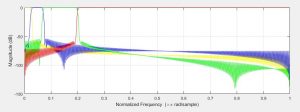
The frequency filtering is a 512-point FIR filter, and as such the cutoff frequencies are pretty sharp. I’ve calibrated the filters to isolate different parts of the audio track. It leads to some very interesting effects. I generate the impulse response using MATLAB, and then turn it into a lookup table for the FPGA to use. Here is a plot of the filters I am using:
Pitch shifting is a basic time domain implementation. I used the BRAM to set up a ring buffer. Data goes into the ring buffer at the audio sampling frequency, but the output pointer moves slower or faster depending on the pitch shifting selected. Linear interpolation is used for fractional samples. I did not expect this implementation to sound very good, but it actually works pretty well. Using the filtering block to filter out the lowest frequencies of the track before shifting makes it sound even better.
The sine function LUT is going to be used to make a new amplitude modulation effect. It is almost complete, but the interpolation between samples is not quite working just yet. When it works, the new effect should be trivial to implement.
Nick Paiva – Weekly Status Update #9
This week I worked on updating the display to use the onboard block ram, wrote a new effect, and tried to get the FFT working in simulation.
The reason I updated the display driver is because using LUTs dramatically increased the compile time. Changing it to use M10k was relatively simple.
The new effect I wrote tries to emulate the clipping we were seeing with our older code. It is called the “deep fry” effect.
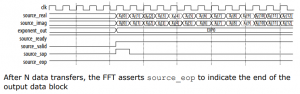
Interfacing with the FFT seems to be relatively simple. It uses a simple ready/valid interface. But, I cannot get it to compile properly in simulation. I spent all day today trying to get it to compile in various simulation software packages to no avail. At this point, I will either abandon the FFT or try to get it working through synthesis alone.
Team A0 – Weekly Status Update #8
This week we worked on polishing off the MIDI decoder, some simple effects, and the display driver. The MIDI decoder is currently working very well, and we are able to use it to control our effects. The display driver is still in the testing stage, but it will not be difficult to get it to print out more interesting information. Overall we have made a lot of progress this week.
Nick Paiva – Weekly Status Update #8
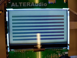
This week, I worked on writing a driver for the display. I started by writing a general SPI driver, and then wrote a higher level control FSM to configure the display. The driver seems to be working well. I plan on updating the driver to print out the current audio signal onto the display.
Here is an image of the test pattern:
Nick Paiva – Weekly Status Update #7
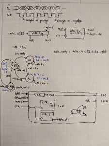
This week I’ve looked into the display driver and FFT more. I’ve tried to compile and run the FFT IP, but haven’t got it working. For the display driver, I’ve begun planning out its verilog implementation and looking at the controller datasheet. The display driver has a simple SPI interface with a few other pins that indicate if we are performing reads or writes and instructions or data. I’ve considered adding a FIFO to make the hardware design of the controller easier, but it doesn’t seem very necessary. The control FSM can be designed such that it only sends data when the hardware driver is ready. Here is my planning document for the display driver so far:
Nick Paiva – Weekly Report #6
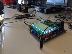
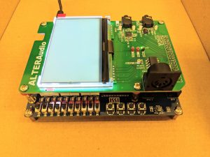
This week I primarily worked on debugging. After a bit of investigation, we discovered a missing connection. This was quickly solved with a bit of soldering. After fixing that connection, the audio pass through worked flawlessly. Here is a picture of the setup:
Nick Paiva – Weekly Status Report #5
This week, one of the things I’ve worked on is assembling the PCB for our project. We then connected the FPGA to power, and everything seems to be working correctly so far. We were able to see MIDI coming into the board on the oscilloscope. Here is a picture of the board while powered on:
I’ve also looked into the FFT further. As it turns out, there is an IP core FFT for the Cyclone V. It seems as though it would work well for our purposes, and would make the implementation process much easier. It seems that we would still have to manage the memory that this IP uses, but that we can easily just pass in samples in natural order.
Finally, I also looked into the display driver more. The display uses a SPI-like interface, and takes data in one bit at a time. It should be relatively easy to write a driver that can send out data in the required format. The harder part is going to be embedding a state machine in hardware that sends all of the required commands to the display. The documentation for the display is not the best, so it is unclear exactly what commands need to be sent to write to pixels on the display. The datasheet for the on board driver chip may be more useful in that regard.
Nick Paiva – Weekly Status Report #4
This week I have looked into how we would implement frequency filtering and pitch shifting. I’ve been reading through this document on an FPGA implementation of the FFT to get an idea of how we would implement this in hardware. Additionally, I’ve been reading up on signal processing theory to get an idea of how we can make this block both efficient and high-quality (low latency, preserves low frequencies).
What I’ve found is that there is a fundamental trade-off between the latency that we introduce into our pipeline and the lowest frequency that we can preserve in our signal. The lower the frequency, the larger the delay. This follows from the idea of Rayleigh Frequency. We need to collect enough points to properly represent a low frequency, and collecting those points introduces delay.
To minimize delay through the pipeline but still preserve the lower frequencies, we should use a window size of 512 points. The total delay through the pipeline would be ~20ms, and we would be able to capture frequencies as low as 94 Hz. Here are some of my notes for this calculation:
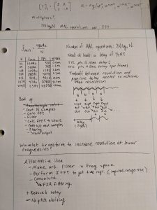
Alternatively, we can solve filtering and pitch shifting in the time domain. For filtering, we could implement an arbitrary digital filter in the frequency domain and then use the IFFT to find its impulse response. Then, it would be a simple matter of implementing a convolution with a FIR (Finite Impulse Response) filter. This method should introduce a smaller amount of delay for the same frequency resolution. For pitch shifting, we could use the Shift OverLap and Add method (SOLA).
The final implementation of this effect will warrant a larger discussion about desired tradeoffs.
Team A0 – Weekly Status Report
We’ve all been busy with job fair stuff so we haven’t gotten too much done this particular week. We have been looking into implementing different effects and drivers, and plan on writing more Verilog and ordering parts for the PCB this week. We hope to have some basic representations of some effects by the end of the week, and detailed plans for others. In class discussions we also clarified the different clock domains and discussed how much performance leeway we have in terms of latency of each dsp block.