4/29 Korene’s Status Report

This week finalized on key housing design and now in process of printing 16 housings, I flipped the fastening joints to the bottom part of the housing for a better fit, and now the finalized sizing is 24mm x 23mm x 20mm (LxWxH) which fits our sizing constraints better. Overall went through 4 iterations of housing design and fittings. Overall process was a bit slower due to access to 3D printer mishaps

Will be well prepared for next week’s demo, just need to attach velcro on the housings. For inductive coiling, we’ll be waiting on a plug in order to connect to a wall outlet. Overall not much testing to be done here, keys do not wobble at all on their own even now so with velcro they should be quite stuck

Zhejia’s Status Report 4/29

This week I worked on the testing and verification of our design and use case requirements, as well as ensuring that my software was able to reprogram the keys successfully. Since last week I developed the communication protocol, this week was focused on the testing of the protocol to ensure that it was reliable and consistent, and could assign all values to all keys without issue. I began by specifying a set of values which each key could take. Next, I generated a few random keymaps to program onto the keys, testing that a mixture of possible key assignments would work without issue on the keyboard. I then tested the functionality of the key to receive duplicate values by programming all 16 keys with the same functionality. I also tested modifier keys such as shift and control, which had a few issues, especially with control having different values for Windows and Mac. However, as there isn’t really a good way to easily detect the system that the keyboard is connected to and have it reprogram itself on the fly, I opted instead to simply document the abnormality for the user to take care of. While this isn’t a perfect solution, because of the time constraints, I was unable to develop a better approach. During the week, I also helped with additional testing, using the keys to assist in my editing of the video final project for another class, which did not end up raising any issues.

I believe I am on schedule, and there is nothing really planned left other than more rigourous testing and the final deliverables.

Next week I plan on finishing the final deliverables for this class, including the report and poster.

Team Status Report 4/29

List all unit tests and overall system test carried out for experimentation of the system. List any findings and design changes made from your analysis of test results and other data obtained from the experimentation.

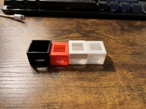
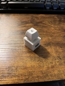
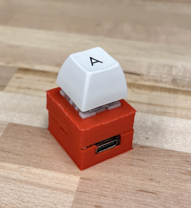
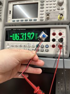
The unit tests done were the testing of Battery Life, Stability, Size, Reliability, Hot-Swappability, and Wireless Connectivity. Battery life was tested by measuring the current draw over a period of time, and determining the average active and passive power draw. Stability was measured by taking a video of the key being pressed while secured to the plate, and measuring the side to side wobble recorded from the video. The size was measured with calipers. The reliability was measured by pressing each key 10 times and ensuring that all 10 keypresses were received. We found that pressing the keys very quickly in this test would cause issues with key presses not registering, so changes to the receiver code were made such that these rapid keypresses would still be registered.

Overall system tests carried out were Layout Freedom, Weight, and Latency. We tested the layout freedom by moving the 16 keys around in various positions and ensuring that all of them were still able to transmit a keypress back to the receiver. We tested the weight by putting all 16 keys and baseplate onto a scale, and recording the resulting weight. No changes were made as a result of any of these tests.

Testing images found in final presentation.

Currently, the most significant risk is that we will not have time to finish the various assignments on time, as we all have finals and other assignments due the same week. However, if we manage our time well, we should be able to finish everything on time.

No updates to the schedule or design requirements have been made.

Ben’s Status Report 4/29

This week, I first worked on the presentation and practiced presenting the slides at home. I also made sure the keyboard receiver was robust enough both in transmission rate and latency to be able to be used as the presentation tools. During the presentation, I noticed that sometimes when pressing the key extremely quickly, it would take multiple keypresses for a key to be registered. After the presentation, I looked into this issue more, as it did not show up during testing. Eventually, I found out that quick keypresses would often times not register correctly. To remedy this, I added a functionality for tap detection, where the key would be pressed and unpressed more rapidly than the time it took to change the characteristic value. The issue was that if two consecutive keyevents were to happen very close together, only one of them would end up registering and being sent to the receiver.  First, I tried decreasing the debounce time but found that even without debounce, it would still only send a single keyevent. Next, I tried briefly going back to a polling method rather than an interrupt method, but that still did not work. Finally, I added a special case where if a keyrelease was detected without it’s corresponding keypress, it would register as a tap, and send a print character command over the keyboard. This ended up working, and even with rapid taps, would still output the correct number of letters. After doing this, I tested with 10 rapid taps, and found that it was much more consistent than before without any lost keys.

My progress is on schedule.

Next week, I hope to finish the final report, poster, and video on time and have nothing go wrong during the final demo.

Korene’s Status Report 4/22

This week did testing and final iterations of key housing.
We finished up tests of the project for latency, inductive charging speed, battery life of keys, portability, and stability. This concludes the final data needed in our report and final presentation slides. We all met up to conclude the tests and I made the necessary calculations in budget to sum-up the purchases of what we’ve made so far. More calculations done to figure out an estimate of our power capabilities done as well. The iPhone slow motion camera was efficient enough to capture the latency, so it wasn’t a problem whatsoever.

Fit wise, the housing is successful but need thicker walls to keep the housing stable. In addition have realized I’ve been using the wrong settings for slicing the print because I’ve been setting the 3D printer to the wrong one in using Cura, which may be a factor into some bugs in printing. Final print will be done Sunday and shall be finishing up the presentation slides. Integration as a whole has been alright, the things left are extra items to make the whole package look nicer in general. Housing being done means we can solidify our weight count for the whole product, as of now it is 371 grams including the previous iteration of 3D housing

We are on track to finishing the projecting and doing my part in contribution.

Team Status Report 4/22

This week we believe the most significant risk is that we will not be able to get enough 3D printed housings to enclose every switch. So far, we have not been able to get the settings down so that the switches housings will not fall apart during or after the print. Additionally, even if we were able to get the prints to work, we would need to print 16 housings without issue. If we end up not having enough time to print all the housings, then the rest of the housings can be made out of paper or cardboard as a last ditch replacement.

We had to change the 3D housing design slightly, making the housing skinnier and with less wall thickness. However, this ended up causing the 3D prints to fail more often, so we had to redesign the housing a third time with the original 2mm wall thickness. These did not incur any additional costs besides the increased 3D printing costs from the prototyping. In fact, since the overall housing is smaller, it would actually be slightly cheaper due to the reduced

The schedule remains the same. Attached below is a picture of the reading of the current the switch draws once the switch is on. This week, we also performed almost all of the testing required to verify that our use case requirements were met. The only test that we did not perform was the test of whether or not the switch would be stable on the base, as we did not have the 3D printed housings or the 3M Dual-Lock on hand. However, this test will be performed next week as soon as we have both of the items.

Zhejia’s Status Report 4/22

This week I worked on the software programmer, the testing/validation, and the slides for the final presentation. For the software, I sketched up and implemented the UART transport protocol to program the keys. The interface first sends a bracket, followed by a comma separated list of key assignments, followed by a closing bracket. I also devised special codes such as RAISE for layer and other modifier keys. I then programmed the software to be able to send this set of assignments to the receiver microcontroller over UART. On the pure software side, I updated the application code to allow the dynamic resizing of the window, as well as the ability for it to remember where each key is after a resize. Next, I worked on the testing and verification of the various requirements. I first tested the wireless charging capabilities by connecting an ammeter in series with the wireless charging module and then measuring the current received by the battery. Next, I tested the latency of the overall system by connecting all the keys and recording them being pressed using the slow motion option on Ben’s phone. The latency was measured from the instance the key was pressed down to the bottom to the time the letter took to show up on the screen of the connected computer. Through this measurement I found that the typical latency is no more than 9 frames in total. Next, I tested the power consumption of the switch assembly by connecting an ammeter in series with a power supply set to provide 3.7v to the battery input of the Seeed XIAO board. Through this method, I found that the keys drew around 6.5mA when active and 0.7mA when sleeping. With this series of tests finished, I updated the final presentation to reflect these changes. Finally, I tested the ultimate range of the BLE receiver by taking a key as far as possible without losing connection. Ultimately, I was able to take the key around 45 feet back before running out of space indoors. However, the key was still connected despite this.

I am slightly behind on the software, as I was supposed to test the integration of the software and hardware components this week, but unfortunately I did not have time to verify. However, since the protocol should be the same, I do believe that there should be minimal issues. I will catch up by performing this test and then fixing any issues that arise before the presentation next week.

Next week I plan on working on the final report and the poster, as well as ensuring that the keys work correctly under a variety of conditions.

Ben’s Status Report 4/22

This week I worked on getting the forwarding of connection and keypress data from the auxiliary BLE receivers to the main BLE receiver. I also modified the software of the main BLE receiver to be reprogrammable over UART. The first thing I did was consider the possibility of setting up a network where the 2 secondary BLE receivers would then connect to the main BLE receiver and forward the keypress data. However, I decided that this idea would not be feasible since the BLE latency from a direct connection was already over half the use case requirement of 50ms at 37.5ms, so adding a second jump for the connection would not be feasible. My solution to this issue was to physically connect the 3 microcontrollers. Since they all have the same pin footprint, I simply soldered headers that allowed the microcontrollers to stack on top of each other, transmitting the key press data in the form of pin signals. Receiver 1 is tied to pins D2-D6 and receiver 2 is tied to pins A2-A6. Whenever a key event is detected, the pin is set to the corresponding level. This adds a negligible latency, as when testing with the 240 fps slow motion camera on my phone, the latency was still 9 frames even when connecting to the bottommost receiver in the stack. Additionally, I implemented the protocol to receive the programming commands over UART. The main receiver will then parse the received string and determine what the new key assignments should be.

My progress is on schedule, and I have finished pretty much everything needed for the project.

Next week I will be working on the presentation, final report, and preparing everything for the demo.

Team Status Report 4/8

The most significant risk to our project currently is the finishing and functionality of the wireless transmitter boards due to their strange behavior, which we have explained extensively in person as well as in our individual status reports. We are managing this risk by trying multiple solutions, including buying smaller coil transmitter boards that come from a different set of testing boards than the set we bought along with reaching out for help to the teaching staff. Our contingency plan in case the wireless charging completely does not work is to have strips of metal as the charger and put contact pads on the bottom of our keys instead.

Another risk is connecting more than 7 keys to connect to one BLE receiver. The new boards that we bought since we thought could raise the limit on the number of BLE connections (which is limited by the allotted memory to each BLE thread), but even after going through the process of raising the limit in the system constants, only 2 BLE connections would ever actually go through. This led us to try working on increasing the limit on our original main microcontroller, but the processes found online are from 5-6 years ago and no longer work. More information can be found in Ben’s status report.  The backup plan in case we cannot increase this limit is to use multiple BLE receivers (3 max).

No changes were made to the existing design of the system.

The schedule is the same except the wireless charging task has been extended and we are working on that and other tasks concurrently.

Here are some pictures of our updated app and app output files:

Here is our newest iterations of the 3D printed housing:

Korene’s Status Report 4/8

This week Question:

  1. Now that you are entering into the verification and validation phase of your project, provide a comprehensive update on what tests you have you run or are planning to run. In particular, how will you analyze the anticipated measured results to verify your contribution to the project meets the engineering design requirements or the use case requirements?
    Inductive coil testing: We’ve been making tests at the outputs of the transmitter coil to see what wave is outputted and what is the output voltage by using an oscilloscope to measure at the two inductor points. This allows us to know if the period is what we expect, if the peak to peak voltage is not being shorted or other reasons it may be lower than anticipated and if our output is still a sine like wave. This is primarily for debugging currently, but later on this will be useful to measure what our power efficiency is when we also measure how much current there is going through as well.
    With power efficiency, we’ll also be testing the duration of how long it takes to charge and this will also be related to the power transfer. One method is through using a stop watch and timing how long it takes to charge fully one (as of now it seems to be relatively quickly through a USB-C, so we may be able to measure the whole battery journey from start to finish). It’s important to measure the entire battery charge as it is a curved relation and not linearly, as it becomes more full, it becomes slower to charge.

    For 3D housing, that is just using calipers to measure. We can see how large it is and then also take into account in usage of whether it is comfortable to type on. Perhaps as an addition to the case we will include a wrist rest as the package of components is quite tall, however this is also a normal occurence in high end keyboards. Stability wise has not appear to be an issue either, but we will take into account of a wobble factor (perhaps measured by multiple people seeing how much effort it takes to knock a key down?)
    This week Progress
    This week I made another iteration of changes to the 3D housing and testing for the inductive coiling to determine what configuration the circuit is in. 

Inductive coil: Issues this week were unfortunately soldering issues to create a good pin output to the breadboard with the inductive coils. A few of the solder pads were ripped off due to uncareful measures, but that is just technical difficulties. That’s caused some slow down with circuit testing

We were able to measure the output of the oscillator chip directly (XKT-412) which we determined is similar to a 555 Timer due to it’s constant output. This denotes that our issues with inductive charging is with the power amplifier. Because of the larger resistance of the smaller coils, it affects how the power is transferred. We are still looking through some literacy to understand what could be helped with this, I’ve been referencing some of my 18-421 notes about common source amplifiers to see what the specific remedy could be and if it is just the common source amplifier or if it could have multiple power amplification stages.

3D Housing: After multiple runs through faulty 3D printing machines and a good print, I’ve determined the walls were made much too thin. I’ve thickened the walls to go from 1mm to 1.25mm and the back wall (which was thinner to account for a longer piece) to be at least 1mm now.

Printing a 1mm wall works fine, but a .6mm wall did not print anything out. Changes shall be printed out on Sunday to see if the results have changed. The picture below is a photo of the schematic of the housing, a hole at the top fit to the key switch to pop out, two sides of locking to fit the top to bottom, and a half hole through the wall for the USB-C port.

I’ve also learned VMware is much more useful than realized so that is a new tool I’ve been using.

Progress has been a bit slow. It’s been a bit frustrating as we thought buying and making changes to a prebuilt board would be easier but I see now that looking at chips like a magic box is not the whole picture. It’s important to know what is necessarily going on in each portion to gain understanding and make changes accordingly. The previous tests have mainly been checking what changes if we change what but that doesn’t necessarily add to understanding as we need to know how each different result is being made.