Zhejia’s Status Report 4/8

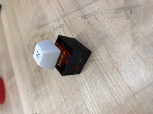
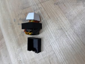
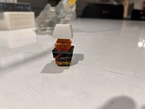
This week, I first worked with Korene to try to decipher what exactly the equivalent circuits for the 2 chips on the wireless transmitter are and we tried to solder wires from the resistors and capacitors on the board so we could connect it to a breadboard and easily swap them out, but one of the resistor positionings was quite awkward, so on both attempts, we ended up ripping the pad off of the board, rending the boards unusable. (We made 1 more attempt after the first on failed). We also did some testing on the connection between the 2 chips and discovered that the first chip, the oscillator, was not the one causing the shorting issue since it still operated fine (outputted a consistent square wave) even when we switched out the inductors or completely removed them, which means the issue is likely with the T5336, which is the one completely lacking documentation but it is likely a power MOSFET, so maybe the issues have to do with it’s operating point?

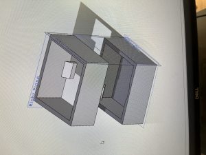
After some setbacks there, I worked more on the keyboard configuration software and implemented freely moving keys, so now the keys can be moved by the user to any location within a rectangular “baseplate” and still function properly.

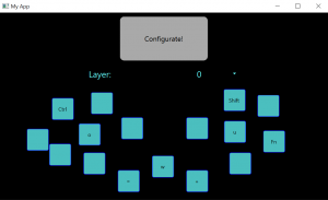
Additionally, I also implemented the save functionality and it now saves the key binds and the positions of the keys to a file so they can be kept for next time. The idea is also to interface this with bens code and only upload a text file to the USB device rather than reflashing the entire board to change just the key binds.

Lastly, I started adding the components to make the user be able to configure different key binds on to different layers. (Typically, personal keyboards allows you to set a key to toggle layers, which changes all the key binds on the keyboard depending on the current layer).

I will be testing the visible wobble of the keys. I will be doing this by recording the typing with a video camera and seeing how much the keys deviate from a central baseline. Additionally, I will be measuring the charging time and rate. Charging time will be measured using a timer and a battery level readout from the keys. Charging rate will be measured using a ammeter connected to the battery charging circuitry. I will also be measuring the costs associated with each key. This will be done by looking at the spreadsheet and figuring out an amortized cost per key for the keyboard.

I am slightly behind schedule for the wireless charging due to the issues with identifying the chips and how they function with the lack of documentation. I am on schedule with the UI create. We plan to discuss with Prof. Tamal tomorrow (Sunday) about issue with the chips.

Next week, I plan to implement most of the functionality of the UI and start interfacing with the microcontroller if there is time. I also plan on making progress and figuring out the situation with the wireless chips, but that progress depends on our discussion with Prof. Tamal.

Ben’s Status Report 4/8

This week I worked on getting more than 7 devices to connect to one central BLE receiver. However, I was ultimately unsuccessful. The first thing I tried was to modify the values in the MbedOS configuration for the Arduino Nano33 BLE boards that I received this week. However, the issue was that to recompile the MbedOS required installing a certain set of depenedencies that were no longer possible. After failing to modify the MbedOS configuration, I instead looked towards trying to modify the ArduinoBLE library to allow multiple connections. I tried changing the ATT_MAX_CONN value first to 8, but that ultimately ended up not doing anything. Then, I dug deeper and looked into what exactly the library was calling, and where connect was failing. I found that the problematic function was in the HCI class’s leCreateConn function, which had would return the value of a call to sendCommand. sendCommand would return the value of _cmdCompleteOpcode, and after some digging, I found that this value was set by the handleEventPkt function, specifically in the EVT_CMD_COMPLETE case. However, I was unable to locate where exactly the value was being written, since the value is assigned to a value passed in through an array that was read into from HCITransport.read. However, I was unable to determine where this value was being read from and how I could ensure that it would not return a result that would lead to the connection failing to be established.

I am still on schedule as it is not essential to have one device connect to more than 7 keys, as multiple receivers can be used. However, I would like to get the number up to at least 8 since that would mean that only 2 receivers would be needed.

Personally, I will be running the tests involving latency and battery life. I will measure latency by recording the process of pressing a key with my phone slow-motion mode, and then counting the frames until it shows up on the screen. Each frame would be 1/120th of a second, so multiplying the frames by 833uS would give me the latency. Next, for battery life, I will be testing the overall battery drain over a period of 1 hour. By measuring the analogue input from the battery pin, and comparing it with the max and min values of the LIPO battery, I will be able to measure the battery level. Then, simply by using the keys for 1 hour I will be able to tell how much battery has drained, and thus how much battery life the device has.

Next week I plan on acquiring more Nano33 IOT boards and developing the connections further. This way, I will be able to test the receiving of more than 7 keys. Additionally, I will also be helping with the housing design and fabrication, and I will be making a few more keys. I can also begin preliminary testing of the latency through frame counting.

Korene’s Status Report 4/1

We completed the project! April Fool’s haha…

This week was quite a bit of debugging for the inductive charging kits, in conclusion we have determined that the kits are specifically tuned to the inductance and resistance of the kit coils. While understandably so, we have been swapping out the resistors and capacitors on the board to make our own observations on what each component has in relation to the inductance values, in which case we are quite stuck on. The board has capacitors that are not seemingly tuned to resonance so this makes it more difficult to determine what changes are needed to be done.

The inductive kits are made of a power amplifier and an oscillator, we haven’t found a direct relation as to what the changes are. We compared with sample schematics but even when replicating a schematic, it was not attuned to the stated inductance but still to the 30uH. We tested with various resistors, capacitances, and creating new coils.

We may look to buying products that fit our size, but may need to lengthen the housing more, however it would be good to have a meeting in order to sort out what could be done with the pcb kits we have.

As for 3D housing, because most of time was spent on figuring out the inductive kits, that is a bit behind, but I plan on printing the changes on Sunday. I added the top cover, adjusted the wall widths, added a USB-C hole, and compacted the width of the total housing to be thinner on one side, however, the other will stay the same.

Team Status Report

What are the most significant risks that could jeopardize the success of theproject? How are these risks being managed? What contingency plans are ready?

Currently some of the risks are that we will be unable to connect all 16 intended keys in an efficient and timely manner. This is because if we are unable to increase the limit on the number of keys that can be connected to a single receiver device, it would mean we would have to network multiple receiver devices together to receive all the signals from the individual keys. While this may work for our proof of concept, it would be impractical for an actual, scaled-up keyboard. To manage this risk, we are considering using one of the Seeed BLE boards as the receiver instead, since the nrf52840 can support up to 20 simultaneous BLE connections.

An additional risk is the wireless charging. While the receiver coil is working, the transmitter coil has been giving us issues all week with it either shorting or not outputting a nice sinusoidal signal. To address this, we plan to buy a new transmitter module with a coil that more closely matches the dimensions of the receiver coil and see if that is able to work. If not, then we plan on redesigning the housing slightly to accommodate the slightly longer receiver that comes with the smaller coil.

A change in the receiver microcontroller may be necessary as the Arduino Nano 33 IOT does not seem to be able to support the number of switches we want connected. Additionally, the width of the housing may need to be increased to accommodate the PCB for the wireless charger. Since we already have the BLE boards, no additional cost is borne there. However, we will need to spend an additional 11 dollars on the wireless charger. The schedule remains the same at this time.

https://ibb.co/S6DHYrk <- Pictures of Coil readings

Zhejia Yang Status Report 4/1

This week I worked on the wireless charging system with Korene. We started out by trying to find out the resonant frequency, but the frequency we read on the oscilloscope was not the resonant frequency of the capacitor and inductor. Specifically, we measured 65kHz for the frequency, and 22uF for the capacitor and 30uH for the inductor, which do not match our resonant frequency. Regardless, we first tried to replace the coil and the capacitor with the resonance coil and capacitor, which worked fine for the receiver, but for the transmitter, when we replaced it, we set the power supply between 9v and 12v at a current limit of 500mA and it would always max the current limit without reaching the required voltage. Additionally, one of the chips would get really hot, indicating that the current was shorting through the coil. After various experiments, we found that for this board, you must both have within 5uH of 30uH and a low enough resistance in order for the transmitter board to not max out on the current draw from the power supply. We tried various things including chaining 4 small inductors together to create a 30uH inductor to test if the inductance alone was the issue, but that did not work since the small inductors have more resistance than the original coil, and the higher the resistance, the more current it would draw from the power supply. Additionally, we looked at various example circuits on the datasheet, and the capacitor that the inductor is supposed to be in resonance with does not change value, remaining constant at 47uF across all the example circuits, which is quite confusing. After discovering that it would impossible to tune either the capacitor or inductor alone to get the transmitter board to work, since the inductor needed to be both lower resistance and higher inductance (thus preventing us from putting multiple coils in series or parallel for them to work), we moved on to trying to understand the resistors on the board and the different pins on the transmitter chip, which can be seen in the datasheet. The thing about these resistors in the example circuits is that there are multiple circuits with the same inductance and capacitance, but slightly different resistor values, due to the difference coil sizes, which I hypothesize has something to due with the extra coil caused by the larger coil size. However, the datasheet only labels each of the pins and we have no idea how the pins work or how they calculate the output frequency. Additionally, there is one circuit in the datasheet (the last one) that almost exactly matches the configuration on our transmitter board, except for the capacitor value, which we eventually changed to match the circuit. The resistors were all the same, except that circuit was configured for 3.7uH coil transmitters, while the current circuit only worked at around 30uH.   this circuit was exactly the same as the one on the board, but when tried to put two of our coils in parallel and attach it, which would give us a 4uH lower resistance coil, the board still did not work and we measured the output through the oscilloscope, and it looked exceedingly strange, and non sine-like.There is a lack of documentation on the functions of the XKT-412 pins and there is no documentation on the XKT-335 which I believe is a power MOSFET. 

I met a roadblock due to the documentation of the chips. As a remedy, I intend to discuss this with the TAs and the professor as to a remedy for this. Additionally, since the receiver board works, I have placed an order for a transmitter board with smaller coils in the hope that it would allow us to sidestep the troubleshooting of the transmitters entirely.

Next week I hope to work on the software and implement more functions. Additionally, I hope to proceed on the magnetic charging with the new transmitter boards. 


Ben’s Status Report 4/1

This week I worked on assembling an additional 5 BLE stacks to bring the total to 9. To do this in an efficient way, I devised a method where the boards could be secured by the header pins into a breadboard to ensure they are aligned correctly after soldering. I also updated the KeyPeripheral code such that the keys will now go into a deep sleep mode after either 10 minutes without activity while connected to the central receiver or 1 minute without connecting to anything after being turned on. This reduces the battery consumption significantly, such that the keys can stay unplugged for multiple days and still be able to connect when pressed again to wake them up. However, I encountered an issue with the Arduino Nano 33 IOT, which is that it only seems to be able to connect to 7 peripherals simultaneously. There doesn’t seem to be a lot of documentation online specifically about this board and how to raise the limit, but there does appear to be some in place for the Arduino Nano 33 BLE. I have tinkered with some of the mbedOS files to increase the thread stack size and also some constants but the number of BLE devices that can be connected simultaneously remains hard capped at 7. Additionally, I have modified the receiver code so that it can identify and connect to new keys after the scan period is over. It does this by storing a copy of all the hardware IDs of each of the keys it’s connected to, and it then periodically attempts to connect to the new modules if it finds that they are available. The updated code can be found on bojuns/FP-Key-A_BLE (github.com)

My progress is on schedule this week.

Next week, I hope to unlock the connection cap to allow at least 8 boards to connect simultaneously to a single receiver. This way, it would be possible to connect all 16 switches simultaneously with only 2 receivers. If this does not end up working, then the next solution would be to make a two tiered design, where the switches connect to an intermediary receiver, which then forwards the signal to the central receiver.

Zhejia’s Status Report 3/25

This week, I first worked on modifying the evaluation boards that arrived from amazon with Korene, desoldering the inductors from a pair of them and measuring the inductance by scraping off the inductive coating and using an LCR meter. Additionally, we also characterized the oscillation frequency the transmitter board was at (around 64kHz). We also tried to follow the traces and figure out which capacitors and resistors were contributing to what, which we mostly figured out, and then we tried to measure the relevant onboard capacitors with the LCR meter to find the ideal resonance frequency, but the calculations ended up way off from the actual operating frequency of 64kHz, so more investigation next week is necessary.

Next, I worked on updating the keyboard driver code on the main microcontroller to accommodate features including:

  • modifier keys (keys that are not visible letters like Ctrl and Shift)
  • multiple key presses at the same time
  • long key presses typing multiple letters (like aaaaaaaa for holding down ‘a’)
  • preliminary different layer support (different ‘layers’ have different keybinds)

Lastly, I started work on a basic GUI for the keyboard configuration software using pyqt6. I ran into some problems with my python installation location and had to spend some time finding where different versions of python were installed in my windows system and editing my path until the installed pyqt6 could be used (I was missing a python3.dll file). After that I created this preliminary GUI:

It functions as you would expect: Configurate configures the keyboard shortcuts typed into the keys (by generating an arduino code file), and to differentiate between the keys, when you click a physical key, the corresponding digital key changes color/lights up. Additionally, I plan to have the keys be draggable to different locations in the UI for users to mimic their current layout if they would like.
However, most of these functionalities are not yet implemented.

I am on schedule.

Next week, I hope to work with Korene to get a pair of evaluation boards to work with our small inductors. This will likely take a long time. If I have more time, I will finish implementing essential features for the configuration GUI.

Team Status Report 3/25

Currently the largest risk is still the wireless charging not working correctly. We received the wireless charging kit this week, but since everyone was busy with their own weekly tasks, the wireless charging was not tested beyond basic verification that it worked.  Additionally, we are worried about the functionality of the wireless charging through the 3D printed housing. We can mitigate the risk of the wireless charging not delivering enough power somewhat by lowering the idle power consumption of the key device, thus allowing the battery to trickle charge with an extremely low current input. As for the housing, it would be possible to make the bottom wall of the housing extra thin to allow for minimal interference with the wireless charging coils. Another risk is that the configurator software may not be able to precisely identify which of the keys is being programmed at any given time. We plan to mitigate this using numbered keycaps on top of each key, such that it would be possible to select a key to be programmed. Alternatively, we could have a system where the user needs to press a key, which would highlight it on the interface and allow the user to set a command.

The spec has not changed in the last week, and no additional costs have been incurred.

Attached below are photos of the key programming interface prototype and the key housing prototype.

Ben’s Status Report 3/25

This week I soldered another 2 BLE boards together and worked more on the software side of things. First, I added debouncing to the peripheral code to ensure that the interrupt would no longer cause a race condition when it was called multiple times in rapid succession due to switch bounce. This caused issues with key reading so I switched the key reading system such that it would toggle the value upon detecting a state change instead, which would save power from reading the keypin all the time. I also played around with the delay in the main loop such that it would connect to the central device quickly without using up too much power. Next, I set up event handlers for the BLE events of connection and disconnection, having them stop and restart the advertising respectively. This would further save on power as the device would no longer need to advertise constantly even though it was already connected to a central. On the central side of things, I fixed up the reconnection such that instead of taking upwards of 30 seconds to reconnect, reconnection could happen within a second or so. Additionally, other keys can still be used while a key or multiple keys are reconnecting since the reconnection does not spin anymore while waiting for a connection like before. However, to facilitate this, I had to also add BLE event handlers for connection and disconnection that would start and stop the scan for the particular device UUID so as to reduce function call overhead for the reconnection of a device. I also helped fit the key stack onto the first prototype of the 3D printed housing. It ended up being too large and without a cutout for the USB, so adjustments will be made in the future.

I believe my progress is on schedule this week.

Next week I plan on working on the central code such that it will be capable of connecting to new key devices beyond just the scan phase. This will mean that if a user brings in new keys, they can be connected right away without a reset of the central receiver. Additionally, this means that if a key was not detected immediately, it can be connected later still.

Korene’s Status Report 3/25

3D housing test fitting was completed and started looking over the inductive charging pcb kits.

The fit was well and had suitable tightness for joints and solid feeling. There’s no tilt whatsoever so it’ll be good to continue the design for it. Perhaps it’ll be beneficial to have a wrist rest so users can type at a more comfortable height, however this is nothing new to the keyboard world as many users have wrist rests in order to use their keyboards that may have a slightly higher profile.

Rough changes were made to the 3D housing and we have adjusted measurements for what to change in the next print out of the housing. We shall make 3D housing changes such as a hole for the USB-C port, adjust the height, and account for the receiver charging pcb. We’ll be on track to complete fulfill the requirements for size.

Inductive charging wise, Zhejia and I have identified what is necessary to change in order to adjust the boards for our usage. We were successful removing the current coils on the boards and now going through calculations to get through the correct capacitor values to replace them. We use the reference circuits from before and are able to identify each piece well.

Next week we’ll continue the process. Perhaps a bit slow this week, but we have a plan for next week.