
For this week, I spent most of my time working on the circuit layer of the mat. I was able to achieve all of my last week’s goals.
For many of the components I soldered, Caio and Spandan helped with gathering, planning and holding the components. Having an extra pair of hands really helped speed up the process. On Monday, we were able to solder and label the FSRs to appropriate length of wires based on where they are to be positioned. We also tested them individually to make sure they worked after soldering. On Wednesday, I was able to design the layout for the circuit. Its picture is shown below.
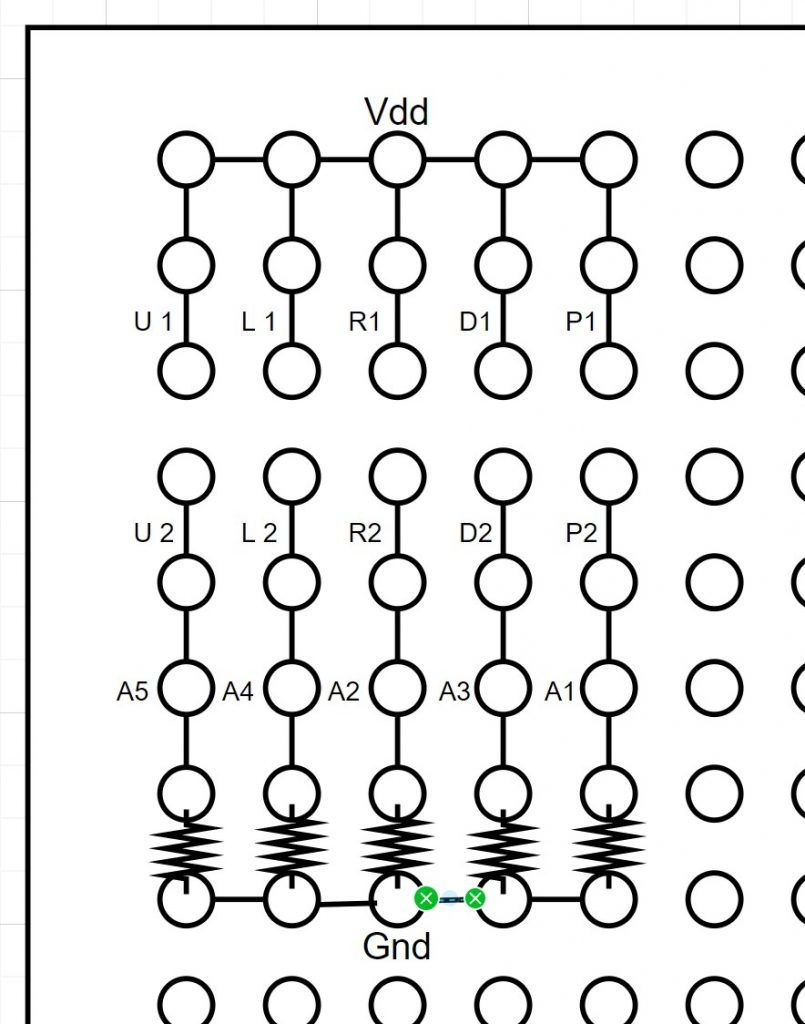
- A5 to A1 refer to the analog pins that they will connected to on the Arduino.
- The letters represent the following
- U: Up FSRs
- L: Left FSRs
- R: Right FSRs
- D: Down FSRs
- P: Pause FSRs
- The number 1 corresponds to the first pins for both FSRs in parallel (for corresponding arrow) and the number 2 corresponds to the second pins.
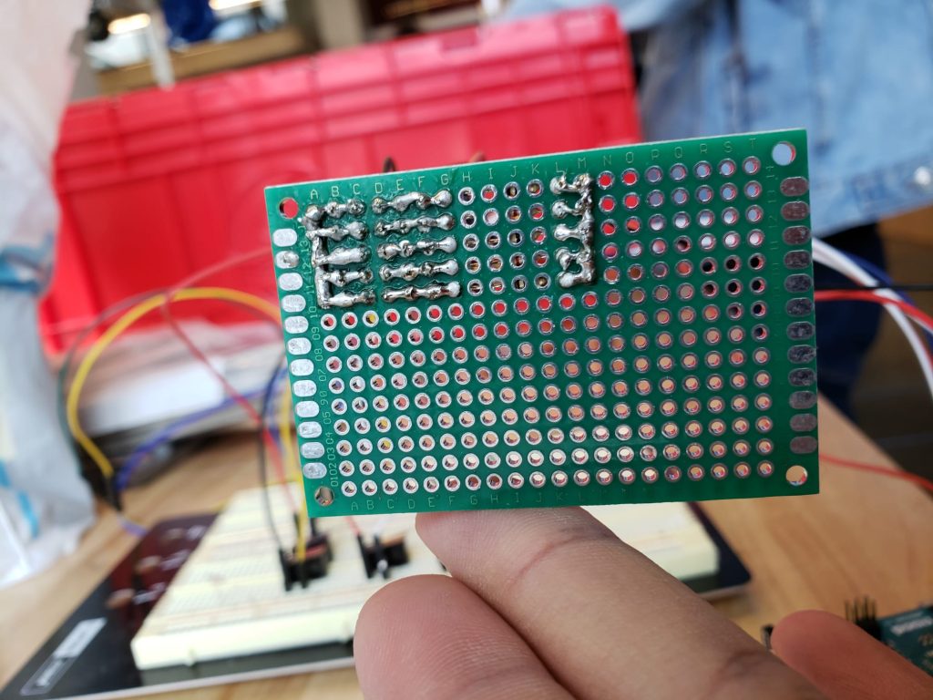
On Friday, we soldered female headers to the perfboard according to the layout above. The reason we decided on female headers instead of direct soldering is because the connections to the FSRs won’t be permanent and can be debugged/replaced more simply if need be. The perfboard was tested with buttons and works properly (similar to how it was tested on breadboard). Here is the picture of how the connections look.
I also learnt how to use the sewing machine in Techspark alongside Spandan from a nice person there. For the upcoming week, I am planning to attach male headers to the ends of FSR wires so they can be put into the female headers easily. With this the circuit layer of the mat should be good to go. I will also be working with Spandan to cut and sew the tarp for the mat. Rest of my effort will be put towards the final presentation.