
Team Status Report
For this week, our team focused on defining the master project timeline, evaluating key system risks, and refining our initial mechanical and electrical hardware architectures.
Project Risks & Management Strategies
Our team identified three primary technical risks that could jeopardize project success and established corresponding management strategies. First, structural deflection in our 3D-printed links under joint motor loads could degrade drawing accuracy. We are running SolidWorks stress and torque simulations on Iteration 1 link geometries prior to printing, with a contingency plan to insert internal aluminum reinforcement rods or increase print wall thickness if excessive flex occurs. Second, dynamic surface geometries could push the arm past its physical reach or into joint singularities. We defined a strict 0.4m *0.4m * 0.4m target workspace and designed our path planner to bound trajectories, utilizing an adjustable mounting base to reposition targets as needed. Finally, subsystem integration between ROS2, microcontrollers, vision tracking, and physical hardware presents a late-stage bottleneck, so we proactively restructured our timeline to include dedicated integration buffer weeks.
System Design Changes
We updated our system block diagram this week to replace traditional stepper motors with smart serial bus servo motors for primary joint actuation. Smart servos provide built-in position feedback controllers and support daisy-chain communication, which drastically reduces physical wire runs and bulk throughout the 6DOF arm structure. While smart servos carry a slightly higher unit cost than bare steppers, they eliminate the need to purchase separate motor driver breakout boards for each joint and significantly reduce wire harness assembly time, keeping overall project costs and risks on track.
Project Schedule Status
The team completed a comprehensive review and revamp of our master schedule this week. We explicitly incorporated dedicated buffer space for system integration and physical hardware debugging toward the end of the term. With these adjustments in place, our overall project progress remains on schedule relative to our updated roadmap.
Team Progress & Highlights
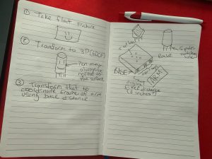
On the design front, the team held a design review forum to critique our preliminary Iteration 1 SolidWorks draft, successfully identifying key structural constraints around shoulder torque distribution, arm reach, and 3D printing clearances. Additionally, we designed a universal object target mounting base equipped with AprilTags. This mounting base allows dynamic target surfaces—such as cups, curved plates, or flat planes—to be secured firmly in the workspace while providing a clear coordinate frame for the vision system to detect relative to the robot base.
- Iteration 1 SolidWorks CAD draft overview showing initial joint and enclosure layout
- AprilTag object target mounting base design diagram