Team Status Report for 09/26/2026

Progress:

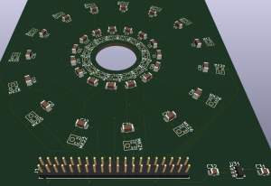
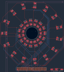
  • Wes: Designed the power subsystem (battery sizing, power connectors) and quantified the mic array’s design requirements (SNR, aperture, sound pressure math) in the Design Report. Finalized PCB schematic/layout in KiCad, passed DRC, got a fabrication quote (~$30/5 boards).
  • Roshni: Implemented the bandpass filter in SystemVerilog (previously Python-only), built automated tests comparing hardware vs. software output, found and fixed two bugs (scaling error, pipeline timing), now matches the Python model exactly.
  • Essie: Stress-tested the heatmap against noise/multiple leaks, found and fixed a false-positive bug, reduced the error rate from 12% to 1.5% (under the 10% requirement) via averaging.

Risks: Several teams’ numbers (array geometry, filter band, noise thresholds) are still placeholders pending real hardware — mitigated by developing independently against realistic assumptions now, syncing once hardware’s in hand.

Design changes: None.

Schedule: On track, all three members.

Highlights: Wes has a fabrication-ready PCB with a real quote; Roshni’s RTL now matches the software model sample-for-sample; Essie’s fix brought the false-positive rate from 12% to 1.5%.

Part A Public Health and Safety

SoundSight reduces physiological risk by letting technicians detect gas leaks, including hazardous or asphyxiating gases without needing prolonged close-range exposure to the leak source. The device is non-contact and passive, it localizes leaks acoustically from up to 10 feet away, so the technician doesn’t need to physically approach, touch, or probe potentially pressurized or hazardous equipment the way contact-based methods require. This directly removes a physical-harm pathway from the inspection process itself.

Part A was written by Essie.

Part B Social Factors:

Project SoundSight addresses the social barrier created by the high cost of existing ultrasonic acoustic cameras, which can run tens of thousands of dollars and are therefore accessible only to large corporations with dedicated reliability teams. By building on a low-cost FPGA platform and commodity MEMS microphones, the device lowers the economic threshold so that smaller manufacturers, municipal utilities, public school districts maintaining aging HVAC systems, and community-owned cooperatives can perform inspections that were previously out of reach. This broadens who gets to participate in proactive infrastructure maintenance rather than confining it to well-funded specialists.

Part B was written by Wes.

Part C Economic Factors:

Our product targets an economic problem for facilities that run compressed air or pressurized gas lines: leaks waste energy and money, and finding them takes time. The U.S. Department of Energy estimates that leaks can waste up to 20 to 30 percent of a compressed-air system’s output, which is a continuing operating cost for any plant that runs one. Routine leak surveys are how facilities control that cost, but the tools available sit at two extremes. Professional acoustic-imaging cameras (FLIR’s Si-series, Distran) are priced for large industrial budgets. Fixed camera systems like the one in Lee et al. (2024) need dedicated hardware at each monitored point, so covering a whole facility would take one unit per fitting. Smaller facilities and budget-limited maintenance teams often end up skipping routine surveys, and they absorb the wasted energy as a result.

Part C was written by Roshni.
Wes’ Status Report for 09/26/2026

26 September 2026

Designed power subsystem for the device, which included estimation of the power consumption of each electrical component. From the system power consumption, I derived a required battery capacity to sustain 2 hours of operation. From that, I chose a 20000mAh power bank to provide 65W of power, enough to avoid any brownouts at 12V, 4A of current draw. Also designed the interface for getting power to the Ultra96-V2, which went through a USB-C to 5.5mm x 2.1mm barrel jack adapter, as well as another adapter to the required 4.75mm x 1.7mm port on the Ultra96-V2.

Quantified all design requirements for the microphone array subsystem, which included equations to derive the sound pressure level created by a gas leak, and the microphone signal to noise ratio (SNR) required for range detection. Also derived the array aperture required for angular resolution of two different leaks. All these quantitative derviations are in the Design Report.

Finalized the PCB components required (the microphones themselves, the exact models of capacitors to use). Downloaded KiCad and designed the schematic for the components. Place and routed the components on the PCB layout, ran Design Rule Check (DRC) to verify that all components are connected. Created gerber files and got a price quotation from JLCPCB ($30) for 5 pieces of PCB.

Schedule Status

The physical hardware implementation is on track, with the PCB design complete. Since PCB fabrication and shipping will take some time, this will be done in parallel with the shipping of other physical components (camera, LCD screen etc.) On track to receiving all materials and starting the build process right after fall break.

Goals for next week:

Verify that PCB schematic and layout is correct (visual inspection of all traces and connections) before sending it out for fabrication. Work on refining the design report. Begin purchasing the components required for the assembly of a prototype.

Roshni’s Status Report for 09/26/2026

This week I took the bandpass filter piece from last week’s Python reference model and implemented it in SystemVerilog, then built a way to prove the hardware version actually matches the software version.

I wrote the filter as a pipelined chain of small multiply-add stages rather than one big calculation, since that structure runs much faster on real hardware. I also set up an automatic export from the Python model that generates matching test files — the same filter settings, a test signal, and the expected correct output — so both versions could be fed identical inputs and compared directly. First run surfaced two real bugs: a scaling error from how the lower-precision hardware numbers get converted back to normal values, and a timing offset where the hardware’s early outputs (before its internal pipeline fully “warms up”) were being compared against the wrong reference samples. After fixing both, the hardware version matched the software version exactly, sample for sample.

For later reference, here’s what I used/researched this week:

  • Icarus Verilog for simulating and running the hardware version
  • SystemVerilog, using a pipelined “transposed” filter structure suited for FPGAs
  • Fixed-point number formatting (converting between normal numbers and the limited-precision format hardware uses)

I am scheduled on track relative to our project roadmap.

For next week, I plan to:

  1. Implement the fractional delay stage in SystemVerilog, verified the same way against the Python reference
  2. Replace the placeholder ultrasonic passband with a real measured leak recording once available
  3. Update mic spacing/count to match Wes’s finalized PCB geometry
  4. Coordinate with Wes to confirm the final array geometry matches the delay-table assumptions

Essie’s Status Report for 9/26/2026

Weekly Status Report — Camera Pipeline (Image Capture)

Accomplishments (with proof):
Built out multi-peak and noisy-data robustness testing for the heatmap rendering pipeline, since prior work only validated a single clean signal. Extended the mock data generator to simulate multiple simultaneous sources and configurable noise, then ran it through the existing overlay renderer to see what broke. Found and fixed a real bug: the renderer normalizes each frame to its own loudest bin, so pure sensor noise with no real leak present was still displayed as a confident-looking red detection blob. Added an absolute detection threshold to gate this out. Quantified the remaining false-alarm rate via 200 randomized trials of a weak signal in high noise: a single-sweep check gave a 12% false-alarm rate (above our ≤10% requirement); averaging 3 consecutive sweeps before thresholding dropped it to 1.5% while improving true-detection rate to 98.5%. Implemented this as an EnergySmoother and wired it into the live demo. Proof: saved test images showing the bug (solid red blobs on pure noise) vs. the fix (clean video), plus the trial-count numbers from the false-alarm simulation.

Status: On schedule. This work also surfaced a concrete, quantified item for the Testing/Metrics section of our requirements (false-positive rate), which we didn’t have real numbers for before.

Next week:

  • Build a live noisy-data demo (currently only tested via saved images, not on camera) to visually confirm the fix in real time
  • Revisit the closely-spaced-sources finding (sources ~4° apart merge into one blob, consistent with the array’s ~3.2° resolution estimate) and note it as a known limitation
  • Continue pushing on the data interface contract with Roshni, since all current numbers (noise floor, threshold, smoothing window) are placeholders pending real hardware measurements

Wes’ Status Report for 09/20/2026

20 September 2026

I primarily worked on researching the geometries required for the 32-microphone array. I then produced the .scr file for Fusion360 Electronics (the PCB design), which took into account PCB routing constraints (such as the placement of the solder pads). I consolidated the “Materials” excel sheet for peripherals that interface with the Ultra96-V2 (camera, LCD display etc.), which included information such as:

  1. Cost
  2. Quantity
  3. Purchase Link
  4. Justification for order

Goals for next week

Place required components onto the schematic in Fusion360, then run all wire routing across all layers of the PCB (including 5V, ground planes). Run DRC and LVS checks across entire PCB board.

Then, submit the order to JLCPCB for a price quotation. Afterwards, submit the 18500 Purchase Request form (sharing the password to the account).

Team Status Report for 09/20/2026

This Week’s Progress:

  • Roshni built a full software (Python/NumPy/SciPy) reference model of the delay-sum beamforming pipeline to verify the algorithm before committing to RTL. Validated against simulated sources at known angles, correctly resolving direction to within the test setup’s 2° resolution limit, and confirmed that a lower-precision (fixed-point-like) version performs just as accurately as full precision.
  • Wes researched 32-mic array geometries, produced the Fusion360 Electronics schematic (.scr) for the custom PCB, and updated the materials/peripherals list for components interfacing with the Ultra96-V2 (camera, LCD display, etc.).
  • Essie built and validated the camera capture pipeline, achieving stable ~30fps live capture with fps logging and automatic frame saving.

Risks & Mitigation:
The main risk is cross-subsystem dependency timing: the beamforming reference model, PCB array geometry, and camera/overlay work all make assumptions (angle count, mic spacing, steering range, output format) that need to converge before integration. We’re mitigating this by having each piece proceed independently against placeholder/mock values now (Roshni’s model uses a placeholder passband, Essie’s overlay work will use mock beamforming output) so no one is blocked waiting on another’s final numbers. We’ll reconcile assumptions once Wes’s PCB geometry is finalized. Secondary risk: hardware not yet in hand (camera, fpga, fabricated PCB), mitigated by validating all logic in software/on substitute hardware first.

Design Changes:
We narrowed the camera/array steering range from a full 180° sweep to a 60–70° forward cone. This was necessary because 180° coverage would require a fisheye lens (adding lens distortion calibration work) and would strain the per-angle cycle budget on the FPGA side. Cost: reduced single-position coverage, making the tool more of a “point-and-scan” device rather than a full-room scanner. This is mitigated by the fact that it matches how commercial acoustic cameras are actually used in the field, and it simplifies both camera selection (standard FOV) and the beamforming compute budget — a net simplification, not a scope loss.

Schedule: On track — no changes to the timeline this week.

Essie’s Status Report for 09/20/2026

Accomplishment

Set up and validated the initial camera capture pipeline for the software/imaging side of the project, using my laptop’s built-in webcam as a stand-in for the C922 (borrowed but not yet in hand — same UVC standard, so the code transfers directly with no changes once it arrives).

  • Set up a Python + OpenCV development environment
  • Wrote and debugged capture.py: opens a camera device, streams live video, and displays a real-time preview window
  • Implemented frame-rate logging (prints live fps to console every 2 seconds) to verify capture stability
  • Implemented automatic and manual frame-saving to disk for later inspection and testing
  • Verified stable capture performance: ~29–30 fps sustained after initial camera warm-up, confirmed via console logs and saved frame inspection
  • Structured the code with a single configurable camera source parameter so switching from the laptop webcam to the C922 next week requires no code changes

I am on schedule. While I wait for camera to come, I can start working on other things.

Next Week

  • Receive and test with the actual C922 camera, confirming capture parameters (resolution, fps) match or need adjustment
  • Build the heatmap-rendering logic using simulated/mock acoustic energy data (angle + intensity values standing in for the eventual FPGA output), including color-mapping and alpha-blended overlay onto live video frames
  • Combine the camera capture pipeline and mock heatmap overlay into a single end-to-end demo
  • Begin coordinating with the RTL/hardware team on the exact data interface format (value range, update rate, number of angle bins) the FPGA will send, so the mock data generator matches the real interface


Roshni’s Status Report for 09/20/2026

This week I built out the software validation layer for our beamforming pipeline before committing anything to RTL. The goal was to get a working, testable reference model of the full delay-sum beamforming chain in Python first, so the algorithm itself is verified before I start writing SystemVerilog.

I built the full beamforming pipeline in software, piece by piece. First, a tool that calculates, for every possible direction and every microphone, exactly how much to delay that mic’s signal — split into a whole-number part (easy to apply) and a small leftover fraction (which needs a bit more work to apply accurately). Second, a filter that keeps only the specific pitch range our leak’s ultrasonic sound lives in. Third, a way to apply that small leftover fractional delay accurately, using a standard interpolation technique, this matches how real published FPGA-based beamformers are built, which I confirmed by checking the research literature before building it myself. Fourth, the part that actually tests each candidate direction: it applies the delays, adds all the microphones together, and does this for every direction in turn, keeping track of which direction produced the loudest combined result. Finally, I ran a test where I deliberately rounded all the numbers down to a lower-precision format similar to what the actual chip will use, just to get an early sense of whether that lower precision would hurt accuracy, before committing to that precision level in real hardware.

To check that all of this actually works, I built a test setup: a simulated ultrasonic sound placed at a few different known angles, “heard” by each simulated microphone with a very precise, trustworthy timing calculation, then run through the whole pipeline above to see if it could figure out the correct angle on its own. The detected angles came out accurate to within the smallest measurable step of our current setup (2 degrees), across every angle tested. Also, the lower-precision version (the one using the rounded-down numbers meant to mimic real hardware) gave results just as accurate as the full-precision version, meaning that, at least so far, using lower-precision numbers on the actual chip likely won’t hurt accuracy.

For later reference, here’s what I used/researched this week:

  • NumPy / SciPy for the signal-processing simulation environment
  • scipy.signal.firwin for FIR bandpass filter design
  • Lagrange interpolation for the fractional (fine) delay stage
  • The coarse-delay + fine-delay (Lagrange/Farrow-style) beamforming architecture used in FPGA-based ultrasound and array-signal-processing literature
  • Fixed-point quantization emulation for an early resource/precision tradeoff check

I am scheduled on track relative to our project roadmap.

For next week, I plan to:

  1. Replace the placeholder ultrasonic passband with the actual measured frequency signature of a real leak recording, once we have one
  2. Update the mic spacing and count in the model to match Wes’s finalized PCB geometry
  3. Begin RTL implementation of the FIR filter module, verified stage by stage against the Python reference model
  4. Coordinate with Wes to confirm the final array geometry matches the assumptions baked into the delay-table math