Wes’s Status Report for 10/17/2026

Accomplishment

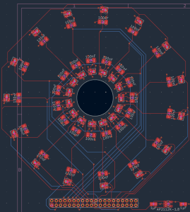
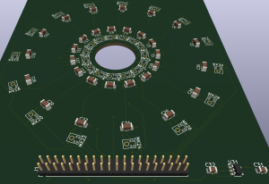
Fabricated PCB arrived at ECE receiving office, as well as all the other components (to be soldered on the PCB). Finalized design report, specifically these sections: use-case requirements, microphone array subsystem (design requirements, design tradeoffs, system implementation). Also filled in section for design and verification.

Did a rough hand sketch of the 3D print mount that holds all the components together. The microphone array PCB will be mounted in front, using four M2 mounting screws. The Ultra96-V2 FPGA will be mounted right behind the microphone array, also using four M2 mounting screws. The Valore powerbank will be mounted behind the FPGA, slotted into a 3D printed slot. The LCD screen will be mounted right behind the powerbank, using four M2 mounting screws.

Schedule

On track

Goals for next week

Solder all components onto the PCB. This will be done in the TechSpark PCB Lab. After PCB assembly, to individually test every microphone for a data signal, before handing it off to teammates for the RTL bringup.

Team’s Status Report for 10/17/2026

Accomplishment

Roshni: Roshni: Retargeted the beamforming RTL to the full 20 to 80 kHz band (384 kS/s, decimation 8, 127-tap filter, 128-sample delay buffers) and regenerated the steering tables for ±52° in 61 steps. All four modules (decimator, filter, fractional delay, scan controller) pass their testbenches against the golden model in both the 384 kS/s and 192 kS/s configurations. Fixed the 192 kS/s filter coefficients and added a clock enable to the filter. The scan controller now outputs a latched 61 × 32-bit energy snapshot with a sweep counter, saturation flag and configurable shift. Also completed a full pass on the Design Report, including verification tests for latency, size and weight, and detection probability.

Wes: The fabricated PCB and all the components to be soldered onto it arrived at the ECE receiving office. I finalized the use-case requirements, microphone array subsystem and design and verification sections of the design report, and sketched a 3D-printed mount that stacks the mic array PCB, Ultra96-V2, Valore powerbank (in a printed slot) and LCD, each on four M2 screws except the powerbank.

Essie: Rewrote the heatmap and capture software to match the final design report (61 angles over ±52°, 105° camera map), running at 30 fps on synthetic data. Added the real data reader and threshold calibration, and drafted a register map and steering ROMs for Roshni to check.

Risks

  • All the components have not arrived and most of work depends on the physical components.

Design changes

  • Normalization: the heatmap subtracts the sweep’s median noise floor before scaling, where the report says to scale by the peak of the full 61-bin sweep. A flat noise floor otherwise tints the whole image, so update the wording in the report.
  • Smoothing Window: The smoothing window is now 4 sweeps (was 3), updated only on new sweeps, and the heatmap subtracts the median noise floor before scaling.

Schedule

On track

Highlights

  • The software now matches the design report end to end on mock data: a 61-angle heatmap overlay at 30 fps, with render time cut from 45 ms to about 5 ms. The real-data path (overlay loader, tear-safe reader, threshold calibration) is ready, so integration only waits on Roshni’s bitstream and register map.

Part A Global Factors:

Pressurized-gas leaks occur in plants everywhere, not only in well-funded facilities, and the cost of commercial acoustic cameras is what keeps many smaller or older plants on manual walking inspections. SoundSight targets that gap with 30 low-cost PDM MEMS microphones and a single FPGA board, aiming to reproduce the core function of a commercial acoustic camera at a lower cost. It needs no network connection, cloud service or specialist setup, so it works in plants with poor connectivity. The output is a colored overlay on live video rather than an audio spectrum, so a technician needs no acoustics training to use it.

Part A was written by Wes.

Part B Cultural Factors:

Plant workplaces differ in safety rules and habits, and the device has to fit them. Many technicians are trained to find leaks by ear or with contact tools, so SoundSight is designed to support that judgment, not replace it. It points to a direction and the technician still confirms the leak by visual inspection or an optical gas imager. Because it is non-contact, a technician stays away from hot or pressurized equipment, which fits safety practices that restrict close contact. Technicians often wear hearing protection, and a visual display works when sound cannot be heard. The interface uses a color overlay and no text, so it does not depend on the user’s language.

Part B was written by Essie.

Part C Environmental Factors:

Leaks waste energy and can release harmful substances. The US Department of Energy reports that leaks sometimes waste 20 to 30% of a compressor’s output in poorly maintained systems, and that proactive detection and repair can bring this below 10%. A 1/4-inch leak at 100 psig costs about $8,400 a year in electricity at DOE’s reference rate. Our device aims to help these poorly maintained facilities find leaks earlier and at low cost, which means less wasted electricity and less release of chemicals, steam or process gas. We also considered the device’s own environmental impact. Our worst-case power estimate is 50 W, so one 2-hour inspection uses about 0.1 kWh, which is small compared with the energy a single leak wastes. The device is rechargeable and uses no disposable batteries.

Part C was written by Roshni.

Next week

Roshni:
Roshni: Build the top level and AXI-Lite register wrapper (including an ID register), then deliver the bitstream, .hwh and a written register map to Essie. Settle the mic clock structure with Wes and add the stored-block energy window to the scan controller. Check Essie’s drafted register map against the RTL.

Wes: Solder all components onto the PCB. After PCB assembly,  individually test every microphone for a data signal, before handing it off to teammates for the RTL bringup.

Essie: Agree the register map with Roshni and swap the mock source for real sweeps. Test the display, cable and camera on the Ultra96, then calibrate the camera and the false-alarm threshold.

Roshni’s Status Report for 10/17/2026

This week I finished the retarget of the beamforming pipeline to the full 20 to 80 kHz band and got every module passing in both the 384 kS/s full-band and 192 kS/s narrow-band configurations. The decimator is now decimation 8 with a 127-tap filter and 128-sample delay buffers. I fixed the 192 kS/s filter coefficients, which turned out to be a 28 to 45 kHz filter, not 36 to 44 kHz, and added a clock enable to the filter so it works with samples that arrive hundreds of clocks apart. The scan controller now steers ±52° in 61 steps and exposes a latched 61 × 32-bit energy snapshot, a sweep counter, a saturation flag and a configurable output shift, which is the interface Essie’s software expects. All four testbenches pass bit-exact or within 1 LSB against the golden model.

I also finished a full pass on the Design Report and re-checked its math against the RTL. I trimmed the longest section toward its page limit.

I am mostly on track. The open item is the integration glue around the verified modules: top level, bus wrapper and bitstream.

For next week:

  1. Build the top level and register wrapper (including an ID register), and deliver the .bit, .hwh and a written register map to Essie
  2. Decide the clock structure for the 3.072 MHz mic clock and the 100 MHz logic
  3. Add the stored-block energy window to the scan controller
  4. Build the time-shared filter and verify it against the parallel version

Essie’s Status Report for 10/17/2026

Accomplishment:

  • Rewrote heatmap.py to match the final design report: 61 angle bins over ±52° (±50° drawn), the 105° camera with the angle-to-pixel map, and 4-sweep smoothing. Render time for a 1280×720 frame dropped from 45 ms to about 5 ms.
  • Rebuilt capture_with_heatmap.py: MJPG 1280×720 at 30 fps, only new sweeps go into the smoother, per-stage timing and a CSV log. It held 30 fps (about 33 ms per frame) on synthetic input. It also ran with display_output.py, tested against a stand-in for the PYNQ DisplayPort driver.
  • Added source.py (mock source, plus a real register reader that loads the overlay, checks an ID register and rejects torn reads) and calibrate_threshold.py (sets the false-alarm threshold from no-source sweeps; 0.50% observed on 17,897 mock updates). Tested the register reader against a fake PYNQ register block: 0 torn reads in about 100,000 reads.
  • Last week 10/10/2026: finialized all the design and drafted the design report

Schedule Status:

On track. Board integration depends on Roshni’s bitstream and register map.

Planned for next week

  • Agree the register map with Roshni, get the  .bit/.hwh, and start the mock-to-real data swap.
  • Test the Mini DisplayPort to HDMI cable against the actual LCD, and confirm the mode it supports.
  • Run the camera on the board at 30 fps, calibrate its field of view and offset, and calibrate the false-alarm threshold on real sweeps.


Team Status Report for 10/3/2026

Accomplishment

Roshni: Replaced the placeholder straight-line array with the real PCB geometry in the beamforming math, no aliasing issue at our target frequency. Got the fine delay interpolator and scan controller working and verified, with bugs fixed in both. Full 30-channel system passed an end-to-end direction test. Started the next pipeline stage.

Wes: Finished PCB placement/routing, added mounting holes, and submitted the JLCPCB order plus all components. Also wrote up the design-report math for the mic array (SPL, aperture sizing, mic noise, SNR).

Essie: Built scan_limits.py and display_output.py, fixed a heatmap FOV bug, added 19 passing tests, and presented at Wednesday’s design review.

Risks

  • Roshni still has an open bug in the decimation stage.
  • Clock frequency still isn’t locked in, and that affects a few other pieces (interpolator, decimation, lookup tables), so it needs to happen soon.
  • The FPGA-to-software interface is still undefined, but we’re closer now that the RTL side is mostly working.

Design changes

  • No changes

Schedule

On track overall. Roshni has one thing to finish next week, Wes is just waiting on parts now, and Essie’s work depends more on teammates’ answers than anything else.

Highlights

Got the full 30-channel system working end to end for the first time — it correctly picked out a known sound direction. PCB design is done and submitted to fab.

Next week

Roshni: find the decimation bug, add full-sweep output to the scan controller, lock the clock frequency, regenerate the lookup tables at full scale. Wes: once the PCB and parts show up, solder everything together in the TechSpark lab and test each mic individually before handing off for RTL bring-up. Essie: get answers on the data interface contract and start swapping in real data, test the DisplayPort-to-HDMI cable on the actual screen.

Roshni’s Status Report for 10/03/2026

This week I replaced the placeholder straight-line mic array with the real geometry pulled directly from the fabricated PCB, which required generalizing the beamforming math to handle it. This also resolved an earlier spacing concern, testing the real layout showed no aliasing issue at our target frequency, confirmed independently by a teammate’s analysis, so no hardware changes are needed there.

I implemented and verified two more hardware modules (the fine delay interpolator and the full direction-scanning controller), each checked against the same reference model as before, with real bugs found and fixed in both. The full 30-channel system passed an end-to-end test, correctly identifying a known sound direction.

I also started the next pipeline stage (raw mic data to usable samples), fixed some bugs there, and am still tracking down one more discrepancy.

I am mostly on track, with one open item carried into next week.

For next week:

  1. Root-cause the remaining decimation discrepancy
  2. Add the missing full-sweep data output to the scan controller
  3. Lock in the hardware clock frequency
  4. Regenerate lookup tables at full deployment scale

Wes’ Status Report for 10/03/2026

3rd October 2026

Added M2 mounting holes to the PCB (2.2mm diameter). Verified that all placement and routing on PCB design is correct and complete. Submitted the JLCPCB order for the minimum 5pcs, as well as all surface-mount / through hole components for the PCB:

1.       1 µF ±20% 50V Ceramic Capacitor X5R 0805 (2012 Metric)

2.       Linear Voltage Regulator IC Positive Fixed 1 Output 600mA SOT-25 (AP2112K-1.8TRG1)

3.       0.1 µF ±5% 50V Ceramic Capacitor C0G, NP0 1206 (3216 Metric)

4.      Harwin M22-2022005 (through-hole pins)

5.      SamTec TCSD-20-D-06.00-01-N (ribbon cable for connecting PCB to FPGA)

6.      SPH0641LU4H-1 Knowles Microphone

Worked on the design report, specifically on the justification for the microphone array design. Added all required equations for deriving the expected sound pressure level at a range of 10 feet, as well as array aperture sizing for angular resolution. Also added all equations justifying the design choice of the SPH0641LU4H-1 Knowles Microphone, deriving the self-noise floor of the microphone, and the operational signal-to-noise ratio picked up by the microphone array (after beamforming).

Goals for next week:

Wait for the arrival of the fabricated PCB and all the components, for surface-mount and through-hole soldering. This will be done in the TechSpark PCB Lab. After PCB assembly, to individually test every microphone for a data signal, before handing it off to teammates for the RTL bringup.

Essie’s Status Report for 10/3/2026

Accomplishment:

  • Built scan_limit.py (frequency-dependent alias-free steering-angle math) and display_output.py (a display-backend abstraction; for now using laptop cv2 today, pynq.DisplayPort once hardware arrives), both wired into the live pipeline.
  • Added 19 passing automated tests across 4 test files ( test_display_output.py, test_scan_limits.py, plus the two existing suites, still green).
  • heatmap.py : Fixed rendered detection to match the real view with 105 degrere FOV. Verified against existing test suites with no regressions, and visually confirmed in rendered output.
  • Presented for the design review on Wed.

Schedule Status:

on track

Planned for next week

  • Get answers on the data interface contract and start the mock-to-real data swap.
  • Test the Mini DisplayPort to HDMI cable against the actual LCD screen.
  • Start the Design Trade Studies section and BOM entries for the written report.


Team Status Report for 09/26/2026

Progress:

  • Wes: Designed the power subsystem (battery sizing, power connectors) and quantified the mic array’s design requirements (SNR, aperture, sound pressure math) in the Design Report. Finalized PCB schematic/layout in KiCad, passed DRC, got a fabrication quote (~$30/5 boards).
  • Roshni: Implemented the bandpass filter in SystemVerilog (previously Python-only), built automated tests comparing hardware vs. software output, found and fixed two bugs (scaling error, pipeline timing), now matches the Python model exactly.
  • Essie: Stress-tested the heatmap against noise/multiple leaks, found and fixed a false-positive bug, reduced the error rate from 12% to 1.5% (under the 10% requirement) via averaging.

Risks: Several teams’ numbers (array geometry, filter band, noise thresholds) are still placeholders pending real hardware — mitigated by developing independently against realistic assumptions now, syncing once hardware’s in hand.

Design changes: None.

Schedule: On track, all three members.

Highlights: Wes has a fabrication-ready PCB with a real quote; Roshni’s RTL now matches the software model sample-for-sample; Essie’s fix brought the false-positive rate from 12% to 1.5%.

Part A Public Health and Safety

SoundSight reduces physiological risk by letting technicians detect gas leaks, including hazardous or asphyxiating gases without needing prolonged close-range exposure to the leak source. The device is non-contact and passive, it localizes leaks acoustically from up to 10 feet away, so the technician doesn’t need to physically approach, touch, or probe potentially pressurized or hazardous equipment the way contact-based methods require. This directly removes a physical-harm pathway from the inspection process itself.

Part A was written by Essie.

Part B Social Factors:

Project SoundSight addresses the social barrier created by the high cost of existing ultrasonic acoustic cameras, which can run tens of thousands of dollars and are therefore accessible only to large corporations with dedicated reliability teams. By building on a low-cost FPGA platform and commodity MEMS microphones, the device lowers the economic threshold so that smaller manufacturers, municipal utilities, public school districts maintaining aging HVAC systems, and community-owned cooperatives can perform inspections that were previously out of reach. This broadens who gets to participate in proactive infrastructure maintenance rather than confining it to well-funded specialists.

Part B was written by Wes.

Part C Economic Factors:

Our product targets an economic problem for facilities that run compressed air or pressurized gas lines: leaks waste energy and money, and finding them takes time. The U.S. Department of Energy estimates that leaks can waste up to 20 to 30 percent of a compressed-air system’s output, which is a continuing operating cost for any plant that runs one. Routine leak surveys are how facilities control that cost, but the tools available sit at two extremes. Professional acoustic-imaging cameras (FLIR’s Si-series, Distran) are priced for large industrial budgets. Fixed camera systems like the one in Lee et al. (2024) need dedicated hardware at each monitored point, so covering a whole facility would take one unit per fitting. Smaller facilities and budget-limited maintenance teams often end up skipping routine surveys, and they absorb the wasted energy as a result.

Part C was written by Roshni.

Wes’ Status Report for 09/26/2026

26 September 2026

Designed power subsystem for the device, which included estimation of the power consumption of each electrical component. From the system power consumption, I derived a required battery capacity to sustain 2 hours of operation. From that, I chose a 20000mAh power bank to provide 65W of power, enough to avoid any brownouts at 12V, 4A of current draw. Also designed the interface for getting power to the Ultra96-V2, which went through a USB-C to 5.5mm x 2.1mm barrel jack adapter, as well as another adapter to the required 4.75mm x 1.7mm port on the Ultra96-V2.

Quantified all design requirements for the microphone array subsystem, which included equations to derive the sound pressure level created by a gas leak, and the microphone signal to noise ratio (SNR) required for range detection. Also derived the array aperture required for angular resolution of two different leaks. All these quantitative derviations are in the Design Report.

Finalized the PCB components required (the microphones themselves, the exact models of capacitors to use). Downloaded KiCad and designed the schematic for the components. Place and routed the components on the PCB layout, ran Design Rule Check (DRC) to verify that all components are connected. Created gerber files and got a price quotation from JLCPCB ($30) for 5 pieces of PCB.

Schedule Status

The physical hardware implementation is on track, with the PCB design complete. Since PCB fabrication and shipping will take some time, this will be done in parallel with the shipping of other physical components (camera, LCD screen etc.) On track to receiving all materials and starting the build process right after fall break.

Goals for next week:

Verify that PCB schematic and layout is correct (visual inspection of all traces and connections) before sending it out for fabrication. Work on refining the design report. Begin purchasing the components required for the assembly of a prototype.