The past 2 weeks, I worked with the team to fine-tune the overall process of the robot and help reduce errors as much as possible. Most of the errors we ran into were related to drifting, slight battery charge change effects, connection issues, or communication issues. Some of them are reliably debuggable (i.e. battery charge or connection issues), but some are random and hard to pinpoint. Overall, the robot performs somewhat reliably but we seek to continue to improve on the process as much as possible for the final demo.
Esther Jang’s Status Report for 11/20
This week, I worked with the team to do testing as described in the weekly status report. We are currently incrementally programming the various steps of our robot’s navigation process which has required a lot of on-hands testing and discussions for problem solving. With Thanksgiving break approaching, we are hoping to be done with our target implementation soon, which may be possible with our current progress.
Esther Jang’s Status Report 11/13
Since my subsystems were completed and have been consistently performing as normal since last week, I did not make any changes to the linear slides nor claw subsystems. All of my work for the week was done with the rest of the team to help implement navigation/integration as described in the team’s weekly status report.
Team Status Report for 11/13
This past week, the team primarily worked collaboratively to start autonomizing the robot. We also had demos during class time where we were able to show the subsystems and receive feedback.
Originally, the code that runs the subsystems for the chassis, slide, and claw systems were separate. When we tried combining them together, we realized that the servo library for the Arduino disables 2 PWM pins on the board (after experiencing a strange bug where some motors stopped moving). This meant that we could not run our entire system together across 2 boards since we needed to use all 12 PWM pins for our 6 motors. We concluded that we either needed to get a servo shield to connect to servo to the Xavier (the Xavier has GPIO pins so the servo cannot be directly connected) or get a larger Arduino board. We were also running into some slight communication delay issues for our chassis with one motor being on a separate Arduino from the others. Hence, we ended up replacing our 2 Arduino Unos with one Arduino Mega 2560 board. Since the Mega board has 54 digital pins and 15 PWM pins, we were able to run all our subsystems on the single board and also eliminated the communication issues across the 2 boards.
For our navigation code, we first focused on being able to get the robot to navigate to an april tag autonomously. Currently, we are relying on being able to rotate and move the robot based on powering the motors on the chassis for a given amount of time. In our tests, we were able to consistently replicate having 1 second of running motors to 0.25m of movement. However, the translational movement is prone to some drift and acceleration over larger distances. Hence, we plan to mostly keep our movements incremental and purchase an IMU to help with drifting disorientations.
Video of 1 second movement to 0.25m translation
Similarly, we found that we were able to fairly consistently get the robot to rotate angles of movement by proportionally associating power on time to our rotational movement.
We then took these concepts and were able to get our robot to navigate to an April tag that is in its field of view. The April tag provides the horizontal and depth distance from the camera center as well as the yaw angle of rotation. Using this information, we wrote an algorithm for our robot to first detect the April tag, rotate itself so it is parallel-y facing the tag, translate horizontally in front of the tag, and translate depth-wise up to the tag. We still ran into a few drifting issues that we are hoping to resolve with an IMU but got results that generally performed well.
Our plan is to have an april tag on the shelf and on the basket so that the robot can be able to navigate both to and from the shelf this way.
We then focused on being able to scan a shelf for the laser-pointed object. To do this, the robot uses edge-detection to get the bounding boxes of the objects in front of it as well as the laser point detection algorithm. It can then determine which object is being selected and center itself in front of it for grabbing.
We tested this with a setup composing 2 styrofoam boards found in the lab to replicate a shelf. We placed one board flat on 2 chairs and the other board vertically at a 90-degree angle in the back.
Video of centering to laser pointed box (difficult to see in the video but the right-most item has a laser point on it):
Our next steps are to get the robot to actually grab the appropriate object and combine our algorithms. We also plan on purchasing a few items that we believe will help us improve our current implementation such as an IMU for drift-related issues and a battery connector converter to account for the Xavier’s unconventional battery jack port (we have been unable to run the Xavier with a battery because of this issue). The camera is also currently just taped onto the claw since we are still writing our navigation implementation, but we will get it mounted at a place that is most appropriate based on our completed implementation. Finally, we plan to continue to improve on our implementation and be fully ready for testing by the end of the next week at the latest.
Esther Jang’s Status Report for 11/6
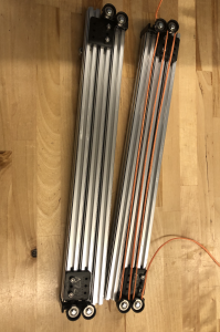
This week, I worked on mounting and motorizing the linear slides on the robot. Both slides were mounted mirroring one another on the chassis. The pulleys were strung with a string that was attached to the motor that would pull the slides. I found that the motor alone was insufficient for lowering the slides, so I added some tension to pull the slides down when unwinding the string by attaching surgical tube between adjacent slides.
Overall, the slides were able to successfully extend and detract with a bar mounted between them as shown in the following clip:
There are some slight issues with detracting fully which I think is related to minor tension issues. The slides were able to individually detract otherwise.
At one point in the week, one set of slides were completely stuck and required significant disassembly to resolve. In order to fix and further help avoid this issue, lubricant grease was applied to the slides.
Finally, I also tested the claws this week and found one to have significantly better grip range and torque than the other. Using the servo code written a few weeks ago, I was able to get the claw to grab a small, light box. The claw was also mounted onto the end of the slides.
Esther Jang’s Status Report for 10/30
Our parts finally arrived this week, so I spent the week building. Unfortunately, I was unable to work in-person for Wednesday and Thursday due to a potential COVID exposure. Hence, most of my work took place on Monday, Friday and Saturday.
I was able to complete building the mechanical aspect of the linear slide system (not including mounting). We did not integrate yet because we ran out of nuts for building but will receive more by tomorrow. The slides seem to extend fairly well although they were getting slightly stuck at times. I think this could easily be fixed with a bit of lubricant. The length of a single slide is 1/3 meter (full meter extrusion cut into thirds), and each set of slides is a mirror of the other.
I also investigated the motor shields with Ludi and was able to control a motor so that it spins at a specified frequency of a specified amount of time, holds, and spins in the opposite direction the same way. This should be approximately the operation we need for the linear slides.
Finally, I attempted to get the claw working with the Arduino code written last week but found that the servo required a voltage of around 6-8V to operate. We will likely need to get a buck convertor to use the claw’s servo.
Esther Jang’s Status Report for 10/23
This week, we placed an order for our parts early this week but unfortunately did not receive any of them yet. As a result, I spent time preemptively investigating software aspects of our hardware.
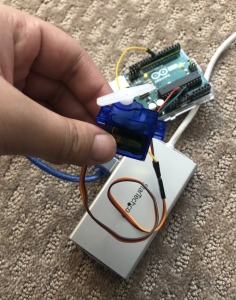
For the claw, I tested controlling a servo through the PWM output on an Arduino board. Although we intend to put them on the Jetson board directly, I tested with the Arduino since I didn’t have access to the Jetson this week. I found that it was very straightforward to run a servo on the Arduino, so we should strongly consider running it there instead of the Jetson if possible.
I also looked into the encoders on the motors and found that they were incremental encoders that have a channel A and channel B pin that needs to be connected to digital pins. In order to keep count of the encoder, we need to compare the signal of the channels with each other as they are out of phase. This also means that we need 5 pins for each motor that uses the encoder – 3 for the motor and 2 for the encoder. As a result, we will likely need to use 3 Arduinos as opposed to our current plan of 2. Overall, using our encoders should not be too difficult as long as we can properly read the pins.
Team Status Report for 10/23
This week, our team finalized our parts order and placed it. We were hoping that at least some of our parts would arrive by the end of the week, but unfortunately did not receive them. We expect to have our parts by the start of the upcoming week and will invest a lot of time to build.
We also had discussions regarding ethics in class and learned a lot in terms of various ethical issues our project may have/cause. For example, we hadn’t considered our laser pointer being misused, our robot damaging the objects it grabs, and if recording others would be problematic.
Esther Jang’s Status Report for 10/9
Last Sunday, I worked with the team to finish up the design presentation and spent a few hours for presenting it. I ended up presenting on Monday and learned a lot from other groups’ presentations.
Throughout the week, I worked closely with the team to reevaluate and discuss solution ideas. In particular, I helped give feedback to and researched the drivetrain design with Ludi in terms of evaluating motor drivers and compiling an initial bill of materials. After realizing that the motor driver we were initially considering had insufficient current output for our motors, the BTS7960 ended up being the best motor driver solution we could find. We also met up today to thoroughly discuss the hardware solutions we are using and ensured that they synthesized together and had appropriate power systems.
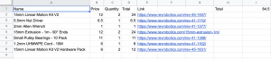
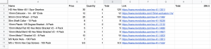
Bill of materials for linear slides + drivetrain:
We also realized that our bill of materials was more costly than anticipated, so we ended up pivoting our linear slides to being powered by Nema 17 stepper motors instead (from the inventory).
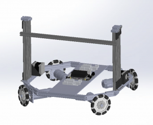
Furthermore, I integrated my linear slide system CAD to Ludi’s completed drivetrain CAD (pictured below).
Finally, I have been wrapping up my research for the servo-controlled claw and plan to spend tomorrow CADing it. Most off-the-shelf parts seem to be unfortunately small and I have seen promising claws made from laser cut parts. In particular, I found the following post to be very useful: https://imgur.com/gallery/LpyW3 and the following book chapter: https://link.springer.com/chapter/10.1007/978-1-4302-6838-3_11. The design of such servo claw systems seems to be fairly standardized (claw arms paired by gears and composed of 2 links).
Esther Jang’s Status Report for 10/2
This week, I spent most of my time doing CAD on Solidworks or researching design options.
I first made considerations for our linear actuation system. Given the height requirement of our robot, I thought it would be best to use a linear motion kit and decided to use the following pulley system described here: https://docs.revrobotics.com/15mm/linear-motion-kit. The primary motivation behind this selection was that it was built to sustain a multi-level cascading height that could reach our height requirement of 3 ft. Furthermore, it is very mounting-friendly for other parts (such as our claw or drivetrain) and price-accessible. This is better than other alternatives that are often significantly more expensive or cannot meet our height requirement (most common problem). I assembled the CAD for this part by using the standard part library from the vendor. The process was time-consuming as I had to relearn how to assemble with CAD, but I believe that it was valuable experience to help me with CADing the remainder of my part of the project.
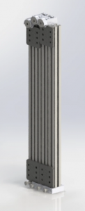
Linear slide system CAD render (based on https://docs.revrobotics.com/15mm/linear-motion-kit/three-stage-cascading-lift)
I also invested several hours into checking the viability of using a vacuum suction gripper, following feedback from a recent meeting to consider it. Using a vacuum suction gripper was a good idea because of the benefit of reducing room for error and for emulating current industry solutions of our idea (i.e. https://www.youtube.com/watch?v=zeKfvUVbO3g&t=4s&ab_channel=IAMRobotics). The main issues I was facing in my research were the following:
- Limited amount of information about the performance of diy suction gripper kits: Most vendors make claims about the performance (i.e. how much load the system can carry), so this was the only basis we could make a decision off of. I was unable to find much solid, unbiased research to support these numbers quantitatively aside from anecdotal videos of performance.
- Limited availability of diy suction gripper kits: Almost all diys I could find were using some version of a standardized suction gripper kit that seems to only be sold from Chinese vendors and with an estimated shipping time of 1 month out in early Nov. There was also a single vendor on Robotshop that sold a potentially promising suction gripper system that uses a syringe+servo system instead of an air pump. The description claimed to be able to have a load of 3oz (0.21lbs) which could potentially be too poor of a performance.
Overall, the vacuum suction idea ended up being too high risk given its limited availability, so we decided to safely abandon the idea in favor for a claw.
Currently, I plan to use a claw system that is similar to off-the-shelf standard grippers (such as https://www.robotshop.com/en/actobotics-perpendicular-standard-gripper-kit-b.html) that is powered by a servo. The reasonably priced off-the-shelf parts do not seem to meet our requirements for objects to grab (small size maximum grip size of 4in and unknown (but likely very light) weights. My current research seems to indicate that CADing and laser cutting the claw is likely the correct direction, so I will continue to look in this direction (i.e. https://imgur.com/gallery/LpyW3).
I believe I am on track as the design research I did was thorough in making sure the chosen designs meet our requirements and are reasonably priced. I will be finalizing the claw idea and expanding upon the electronic hardware evaluation done last week by early tomorrow (in time for the design presentation).