Ludi Cao’s Status Report for 10/30

The robotics parts arrived earlier this week. I assembled the drivetrain chassis shown in the pictures below.

We are short on screw nuts, so I ordered more which should arrive in a day or two to add more securing between parts. I also tested speed control with the BTS7960 motor shield. I wrote the program such that the wheel speed changes based on the number inputted to the Serial monitor. Last week, I tested information passing between the Jetson Xavier and arduino through Serial.monitor as well and it worked. Hence, integration between the modules is promising. 

https://www.youtube.com/watch?v=VdI3qAsY-3I

Esther Jang’s Status Report for 10/30

Our parts finally arrived this week, so I spent the week building. Unfortunately, I was unable to work in-person for Wednesday and Thursday due to a potential COVID exposure. Hence, most of my work took place on Monday, Friday and Saturday.

I was able to complete building the mechanical aspect of the linear slide system (not including mounting). We did not integrate yet because we ran out of nuts for building but will receive more by tomorrow. The slides seem to extend fairly well although they were getting slightly stuck at times. I think this could easily be fixed with a bit of lubricant. The length of a single slide is 1/3 meter (full meter extrusion cut into thirds), and each set of slides is a mirror of the other.

I also investigated the motor shields with Ludi and was able to control a motor so that it spins at a specified frequency of a specified amount of time, holds, and spins in the opposite direction the same way. This should be approximately the operation we need for the linear slides.

Finally, I attempted to get the claw working with the Arduino code written last week but found that the servo required a voltage of around 6-8V to operate. We will likely need to get a buck convertor to use the claw’s servo.

Bhumika Kapur’s Status Report for 10/30

This week I was able to start working on the camera and Jetson Xavier setup. We got the Xavier setup earlier in the week, and I worked on getting the Intel RealSense Viewer setup on the Xavier. Once that was setup, I worked on downloading the necessary Python libraries on the Xavier that are needed to use the Intel RealSense data. That took me some time as I ran into many errors with the download but, the library is now set up.

Once the viewer and the library were setup I began working on actually using the camera’s stream. I ran many of the example scripts given on the Intel RealSense website. Two of the more useful scripts that I was able to run were a script for detecting depth of object in the stream, and a script for using depth image to remove the background of an image. The results are shown below:

The first image shows the result of running the depth script, which returns the depth of a pixel in meters. The x,y, and depth information is printed out. The second image shows the result of using depth information to remove the background and focus on a specific object.

Next week I plan to use these scripts in conjunction with the edge and laser detection algorithms I have written, so that the robot can use that information to navigate.

Team Status Report for 10/30

This week we received all of the parts that we ordered, and began producing our robot. We setup the Jetson Xavier and Bhumika has been working on the computer vision aspect of the project using that. Ludi was able to assemble most of the chassis. Esther build the linear slides, and both Ludi and Esther are working on getting the motor shields to work. Next week we will continue to work on assembling the robot, and integrating the different components such as the chassis and the linear slides. Overall we are satisfied with the progress we have made so far.

Ludi Cao’s Status Report for 10/23

This week I worked on the software portion of the motor controller. I completed the initial setup for the Jetson Xavier, and installed the packages we would need for our project. Since the computer vision algorithms would be run on python, and the Arduino code is in C/C++,  I wrote the communication channel between the Jetson Xavier and the Arduino.

The screenshot shows how the two entities communicate with each other when fed in some data. I also have written the logic of the drive train, specifically the omnidirectional logic for the different motors to move in different directions. I also briefly looked into the software code of adding encoders to our motors. Since the Intel Realsense cannot detect an object in a short distance frame, the drive train would need to travel a fixed distance after applying the computer vision detection from far away. Adding encoders would provide closed-loop feedback to ensure high accuracy. Since the hardware parts have not arrived yet, I am not able to tune any parameters of the skeleton code. Hence, the project is delayed behind schedule, but hopefully, the hardware parts would arrive early next week, and I am able to construct the robot and have an initial test of the motors and drive train accuracy. 

Esther Jang’s Status Report for 10/23

This week, we placed an order for our parts early this week but unfortunately did not receive any of them yet. As a result, I spent time preemptively investigating software aspects of our hardware.

For the claw, I tested controlling a servo through the PWM output on an Arduino board. Although we intend to put them on the Jetson board directly, I tested with the Arduino since I didn’t have access to the Jetson this week. I found that it was very straightforward to run a servo on the Arduino, so we should strongly consider running it there instead of the Jetson if possible.

I also looked into the encoders on the motors and found that they were incremental encoders that have a channel A and channel B pin that needs to be connected to digital pins. In order to keep count of the encoder, we need to compare the signal of the channels with each other as they are out of phase. This also means that we need 5 pins for each motor that uses the encoder – 3 for the motor and 2 for the encoder. As a result, we will likely need to use 3 Arduinos as opposed to our current plan of 2. Overall, using our encoders should not be too difficult as long as we can properly read the pins.

Team Status Report for 10/23

This week, our team finalized our parts order and placed it. We were hoping that at least some of our parts would arrive by the end of the week, but unfortunately did not receive them. We expect to have our parts by the start of the upcoming week and will invest a lot of time to build.

We also had discussions regarding ethics in class and learned a lot in terms of various ethical issues our project may have/cause. For example, we hadn’t considered our laser pointer being misused, our robot damaging the objects it grabs, and if recording others would be problematic.

Bhumika Kapur’s Status Report for 10/23

This week I worked on two things. First, I worked on getting our camera, the Intel Realsense setup. We were able to obtain a new camera with its cable, and get it somewhat working on one of our team member’s laptop, and it also worked well on our TA (Tao’s) laptop. The next step is to connect the camera with the Jetson Xavier and get it setup there.

I also worked on the laser detection algorithm. I tried a few different methods that I found online with varying results. The first algorithm that I tried only used the RGB values of the image, and manipulated these values to calculate the degree of red compared with the other pixel values.  The results are shown below, where the laser is the circular spot:

The next algorithm I used involved using the HSV values and thresholding then, and then anding these values to find the laser in the image.  This method seemed to work, but need more testing to determine the best threshold values. The results are shown below, with the laser in pink:

Overall both algorithms were able to detect the laser in a simple example, but I will need to perform more testing to determine which algorithm is preferred when shining the laser on an object. Next week, I plan to work on setting up the camera and improving on this algorithm.

Ludi Cao’s Status Report for 10/9

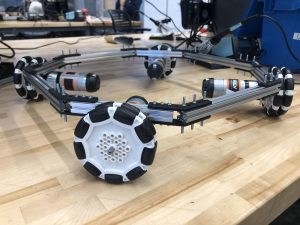
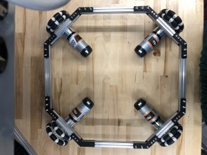
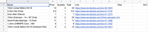
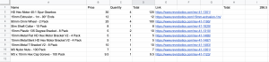
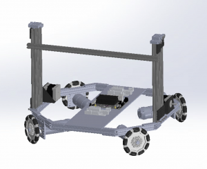
At the beginning of the week I had an extensive discussion with my team to finalize the specific hardware we need to order and the associated bill of materials. We realize that budget is a concern, and based on that I slightly modified the base of the robot chassis to be smaller and more compact.

The base is now roughly 35cm * 35cm, where the straight extrusion on the sides are 20cm, and the diagonal extrusions connecting to the wheels are 12cm. Reverting to a smaller size would save up a log of cost material, and also make the linear shaft system steadier. Since the height of our robot is nearly 1 m high, and our claw system would stretch forward to reach an object of 1.5 lbs at max, I was initially concerned that the robot might “tip” forward when reaching out to a heavy object. However, based on the relative distances and weights of components, based on the lever rule in physics, the mass times distance towards the side of the robot is roughly 6 times as heavy than the same calculation done on the object side. Therefore, the need of a counterweight is also removed from my initial prototype of the robot.

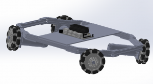
I also did some other metrics calculations to confirm our system would meet our technical requirements. We aim to have the robot move at a speed of 0.5 m/s when not performing other computations. Based on our motor specs: 150 rpm and a wheel diameter of 90mm, according to the equations f = 2 pi f and v = rw, we derive that the ideal speed of our robot is 0.7065. Yet, our robot has a considerable weight, so taking a rough 20% deduction, our robot can still travel at a speed of 0.5625 m/s. Hence, I would anticipate our robot would just meet the requirements, and it would be interesting to experiment the results. I also calculated the power our system would consume, and find that our battery can last around 3.5 hours per charge where the robot is operating at full capcacity. This confirms that our robot is efficient enough to be used multiple times.

I am on schedule, although I didn’t find much time to explore the software side of the drivetrain, and we are a bit behind on ordering the materials. Next week our team would focus on the design report, and we would send the materials next Tuesday and hopefully have some parts delivered by then.

Esther Jang’s Status Report for 10/9

Last Sunday, I worked with the team to finish up the design presentation and spent a few hours for presenting it. I ended up presenting on Monday and learned a lot from other groups’ presentations.

Throughout the week, I worked closely with the team to reevaluate and discuss solution ideas. In particular, I helped give feedback to and researched the drivetrain design with Ludi in terms of evaluating motor drivers and compiling an initial bill of materials. After realizing that the motor driver we were initially considering had insufficient current output for our motors, the BTS7960 ended up being the best motor driver solution we could find. We also met up today to thoroughly discuss the hardware solutions we are using and ensured that they synthesized together and had appropriate power systems.

Bill of materials for linear slides + drivetrain:

We also realized that our bill of materials was more costly than anticipated, so we ended up pivoting our linear slides to being powered by Nema 17 stepper motors instead (from the inventory).

Furthermore, I integrated my linear slide system CAD to Ludi’s completed drivetrain CAD (pictured below).

Finally, I have been wrapping up my research for the servo-controlled claw and plan to spend tomorrow CADing it. Most off-the-shelf parts seem to be unfortunately small and I have seen promising claws made from laser cut parts. In particular, I found the following post to be very useful: https://imgur.com/gallery/LpyW3 and the following book chapter: https://link.springer.com/chapter/10.1007/978-1-4302-6838-3_11. The design of such servo claw systems seems to be fairly standardized (claw arms paired by gears and composed of 2 links).