Joshua’s Status Report 3/28/2026

Electrical Developments:

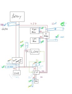
Before getting to the CADDing, I wanted to be sure how we were wiring this all up, and then therefore what wiring space I would need to take into account while making the housings.

IMU / I2C wirings:

H-Bridge specific Wirings:
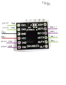
All components wiring diagram updated to included capacitors:
Y-splitting the battery connector out so we can easily distribute to all other parts.
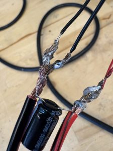
There’s more, and I believe we may have some videos for our team post, but basically I oversaw all the electrical work (so it was a group effort in soldering up all our parts, but I was delegating, as this is the part we’ve ascribed to me having ownership over), and it’s all looking great!! This last complicated one we only did for one battery, as it felt a bit sketchy, but all our motors and sensors have their wires and pins soldered up!

I know we spent a lot of time considering all components, and making sure that it would all work. However, I was pleasantly surprised that when we actually put it all together it just worked. Props to brooks for getting software working near first try!

Housing Developments:

Due to spending more time on the electrical work, the housings are unfortunately not finished yet. It is looking unlikely that a first print will be finished by Monday, but I want to still have a 3D model to show for the presentation (to also talk about improvements/extensions), then a print done Wednesday.

A few new things that also caused reworking:

1) our motors are 20 RPM, not 20 RPS. So a gear up is in order. Figured out how to make and port over gears, so now just need to figure out what ratio we actually want/need. (see double_helix gear below, using a plug-in for onshape I found:)

2) we need to order wheels / a ball caster. I thought we could 3D print them, for some reason, but for good grip we really should just order them. I found a good set that should work for all 4 bots, and submitted an order to them. It will take some fenagling to get it on nicely.

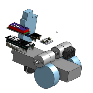
3) our electrical components are rather loose. I was thinking we would make use of the pins as a sort of holder for them, and then use female to female jumper cables, but this takes up a lot of space. Instead, we will be using a series of empty holed PCB boards with mounting holes. This makes it much easier to connect all our components together and hold them in a compact fashion.

current tentative placement of all electrical components (plus wheels) in onshape:
Team’s Status Report for 03/28/2026

Risks:

There are no major new risks at the moment. We are proactively mitigating the primary risks associated with full robot assembly by continuing our strategy of modular integration testing. For example, this week we successfully wired up both the IMU and the TF-Luna LiDAR to run simultaneously on the ESP32-S3 using the same shared I2C GPIO pins. This important step confirms that our data interconnects and initial module interactions are stable before committing to final assembly. Looking ahead, we still need to begin soldering components directly to the PCBs and attach the buck converters to the remaining battery connectors. Therefore, our main remaining risk is the potential for unforeseen hardware or power distribution issues arising during this final, permanent physical integration phase.

Design and Schedule Changes:

There have been no fundamental changes to our overall design path or timeline. However, we did introduce a highly effective architectural enhancement: utilizing a micro-ROS middleware layer encapsulated in Docker to better bridge the raw, hardware-level sensor data with the live UI. This architectural enhancement solved a difficult integration problem without altering our core design. We remain on schedule overall; while UWB trilateration is still being finalized, we have successfully gotten the motors, H-Bridge, IMU, and LiDAR operational.

Adrian’s Status Report for 03/28/2026

The primary focus this week was bridging the gap between hardware-level sensor data and the live UI by getting real-time data to at least show up there rather than just the terminal/Arduino output. This involved stabilizing the ESP32-S3 firmware for distance sensing and implementing a robust micro-ROS middleware layer using Docker to ensure the frontend can reliably consume live LiDAR feeds without direct serial dependencies.

The metric on the bottom left represents the distance between the LiDAR and iPad, where the occupied cell is marked at around 30 cm. ESP32-S3 firmware (PlatformIO) reads a TF-Luna over I2C and publishes distance on micro-ROS (/catombot/lidar/front/distance_cm). Then the UI repo documents a live LiDAR bridge: micro-ROS agent in Docker, optional npm run bridge:lidar with ROS topic echo → Server-Sent Events, or --source=serial using PlatformIO serial monitor parsing. The UI can be opened in live mode (?lidar=live and related env vars).

A small read_serial.py script also helps validate raw serial timing and baud settings on macOS/Linux.

Additionally, micro-ROS Docker container was especially valuable because it turned a difficult hardware-to-browser integration problem into a much more manageable interface problem. Instead of trying to make the frontend understand ROS-native or serial-native behavior directly, the container provided a stable middleware layer that could ingest the live sensor feed, preserve useful metadata, and expose it in a form the UI could actually consume reliably.

The next steps are to calibrate LiDAR so ranges and geometry match the real map scale and robot frame, and to fuse IMU data into pose and speed estimates so on-screen motion reflects how the CatomBot actually moves. Depending on progress with UWB range triangulation, I will also surface that data in the UI (e.g. anchors and fused position) and use it to tighten FREE vs OCCUPIED classification and stabilize frontier cluster centroids that guide exploration

Brooks’s Status Report for 03/28/2026

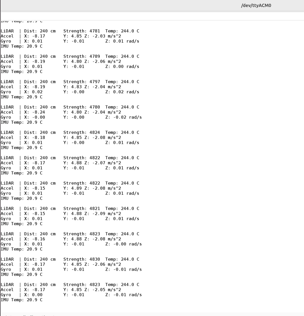
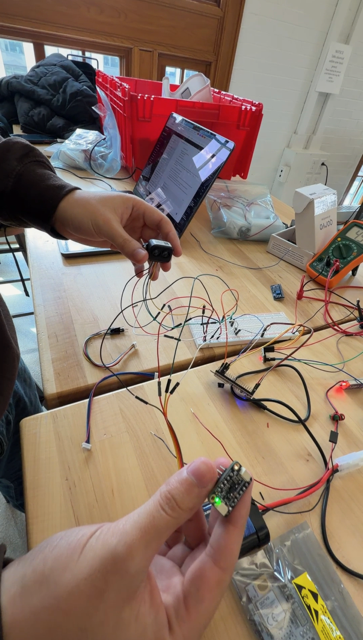
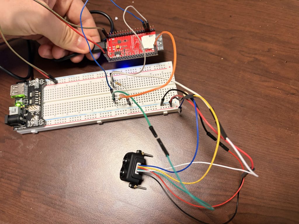
This week I worked on getting UWB trilateration working, and my goal is to have it finished tomorrow. I also helped get the motors / H-Bridge and the IMU working. I also helped with soldering a lot more pin headers to all of our components, so we now have almost all the physical components together, we just need to start soldering to the PCBs and to solder some of the buck converters to the other battery connectors. We also did some basic integration testing where we wired up both the IMU and TFLuna together and ran them both at the same time. Both are connected to the ESP32S3 on the same GPIO pins to communicate over I2C. Lastly, I finally was able to figure out how to get ROS working on my groupmates’ computers so that they can now run the micro-ROS agent on their systems.

LiDAR and IMU Readings
LiDAR and IMU Wired Together

We are on schedule, but tomorrow the group as a whole needs to spend a lot of time together to ensure we are ready for the interim demo and that our systems are in a good spot to show off.

Next week I hope to complete locationing for the survivor tag, which will involve having one non-anchor UWB board being tracked in 2D space, and then having it also range with an AirTag or other UWB board to act as the survivor tag, and then produce the location of the tag by inferring position relative to the non-anchor or tag board.

Team’s Status Report for 03/21/2026

Risks:

There are no new risks at the moment. The biggest risk we anticipate has to do with potential issues coming out once we are able to assemble a bot, e.g. we find out that the voltage regulator is unable to support all the devices, etc.. The main way we are mitigating this is by testing components together when we can, such as testing UWB ranging where at least one UWB board is solely connected to the ESP32S3, which allows us to at least confirm that interconnect between individual modules works. At full bot assembly, this will save a lot of time debugging potential issues since we’ve verified which individual parts should work together.

Design and Schedule Changes:

There have been no changes to our overall design, we are still following the same path as before. Similarly, no changes have been made to the overall schedule. Completion of global frame formation has been pushed to Monday, but the following deliverable of trilateration is on track to be finished at the same time. Therefore, we are still on track for the upcoming interim demo.

Photos:

Initiator board (connected to ESP32S3) returning TWR info
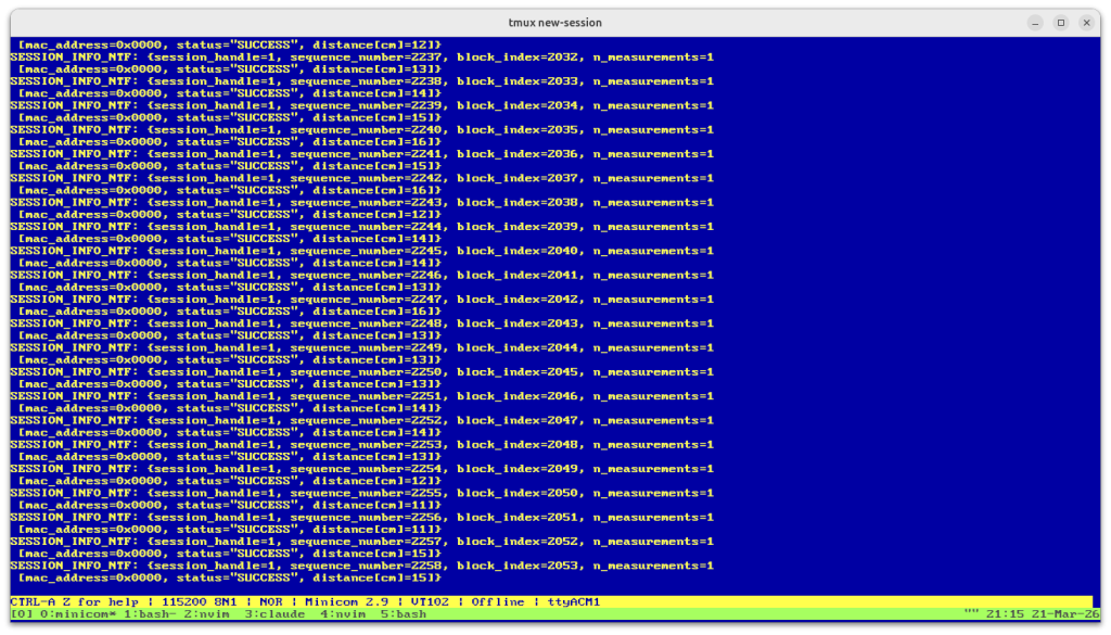
UWB Responder (Connected to computer via USB) Serial Output
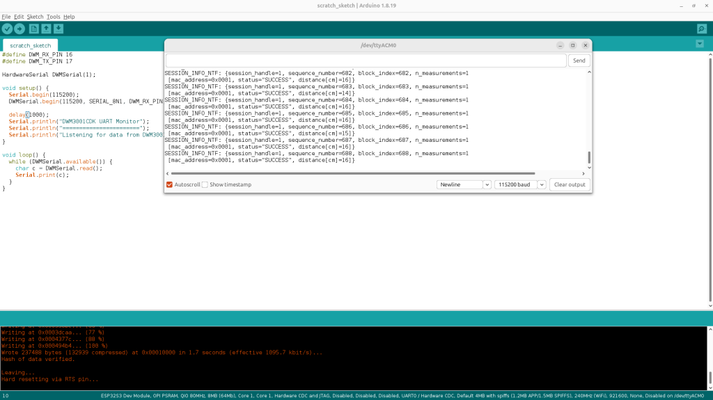
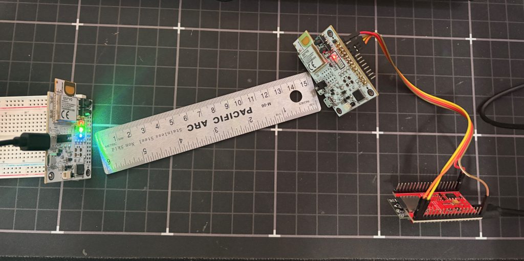
UWB Ranging ~15cm away. Left board is responder (powered by USB), right board is initiator (controlled and powered by ESP32S3)

UI:

LiDAR Working:

LiDAR wired up to the ESP32S3. Confirmed ESP32S3 was able to read measurements.
Schematic for LiDAR wiring above.

Brooks’s Status Report for 03/21/2026

This week I was able to create the ranging UWB ranging pipeline between one of the UWB modules and an ESP32S3. In order to do so, I had to solder some header pins to the DWM3001CDK, and then hooked up the UART pins, 5V, and GND pins to the ESP32S3. The ESP32S3 sends CLI commands and then receives ranging data over UART. After this, I setup one DWM board to be an initiator for TWR while another was setup as a responder. The initiator was connected to and powered solely by the ESP32S3, while the responder was connected to my computer over USB. With this setup, I confirmed from the ESP32S3’s serial monitor that the ranging data was successfully being picked up. Lastly, I also set the UWB modules to be roughly 15cm away from each other and confirmed that the measurements were, on average, accurate.

TWR Ranging Setup. Left board is responder, right board is initiator
Initiator board (connected to ESP32S3) returning TWR info
UWB Responder (Connected to computer via USB) Serial Output

Regarding scheduling, I am behind on implementing formation of the global frame as this was supposed to be completed by today, however to compensate I plan on spending additional slack time tomorrow working on this. The primary concern in falling behind on this task is that the trilateration implementation requires the anchor boards to have coordinates assigned to them, and so a coordinate system is needed. However, this can technically be solved temporarily for trilateration testing purposes by assigning an arbitrary origin and axes. Therefore, my plan is to allow myself until Monday night to complete global frame formation. If I’m unable to completely finish it by this point, then I will move onto implementing the trilateration algorithm and plan to test by assigning a corner of the Hamerschlag room that our group works in, and define the axes myself. I gave myself longer than what should be necessary to implement trilateration (the algorithm is pretty straightforward), so I hope to finish that part early, giving me time to return to global frame formation if need be.

As mentioned above, the deliverables I hope to complete next week are global frame formation and trilateration, but I will prioritize trilateration if global frame formation takes me longer than Monday to complete.

Adrian’s Status Report for 03/21/2026

My plan this week was to wire Vector Field Histogram (VFH) into the live navigation loop and make frontier-based exploration visible on the tactical map so the operator can see both where coverage is growing and where the swarm is pushing next.

Across the four images, exploration grows from a small green pocket with a partial red wall outline to a fully mapped space whose OCCUPIED boundary cells form a complete red perimeter where LiDAR marks FREE interior and stamps OCCUPIED where rays hit the map edge. Teal trails stay in free space and skirt those red cells because VFH turns the global heading toward each frontier centroid into a locally safe steering angle via a polar obstacle histogram, then kinematics plus grid collision keep bots out of walls. The heatmap blooms track visit density and pile up at the leading edge of the dark UNKNOWN region, matching frontier detection (FREE cells next to UNKNOWN cells); as the frontier collapses, the map fills with green and the bright coverage fades, showing frontier-following exploration with obstacle-aware motion end to end. Once the entire map is covered with labeled/colored cells, the bots return to the base station without hitting OCCUPIED cells along the way.

VFH is implemented in src/exploration/vfh.ts, which builds a 72-sector polar obstacle-density histogram from nearby OCCUPIED cells, thresholds sectors into a blocked mask, finds contiguous free “valleys,” and picks a steering heading that stays aligned with the global goal while avoiding obstacles. The simulator (mockDataSimulator.ts) now uses this on every step: for each bot, it computes the heading toward the assigned frontier centroid, runs computeVfhHeading, then projects a short virtual waypoint along vfh.steeringHeading so the existing proportional kinematics controller tracks a VFH-safe direction. Map polygon bounds and grid-based collision resolution still apply after the move, so local avoidance and global feasibility stay consistent. Unit tests in vfh.test.ts cover histogram construction, valley finding, and end-to-end computeVfhHeading behavior.

Note that currently, the full histogram is not drawn as a separate UI panel; it powers motion in the sim. Exposing a small polar plot or debug overlay would be optional follow-on work.

Frontier logic is unchanged in principle, but the store now carries explorationGrid and frontierClusters each tick, and MapCanvas.tsx layers them so the algorithm is visible:

Status & next steps
Integration is on track: VFH is in the control loop, frontiers are fed from the same grid the sim uses, and the map reflects both. Next: optional debug visualization for the live histogram, tighter tests between VFH + multi-bot assignment under clutter, and (if needed) performance tuning of sector count / active radius for the target update rate.

Joshua’s Status Report for 3/21/2026

CAD Progress

Started CAD files for the robots. For this week, mainly searching for existing models and importing all parts I could find. Then, measuring and making approximate stand-ins for the remaining parts. Also shared it with my teammates, so they can see the progress as we go, and maybe also help the design process if need be.

I have already been considering how we will be attaching things, gathering standoffs and such. The next step is to arrange the models around for proper CAD housings.

Electrical Progress

We got our LiDAR working! Adrian and I are mostly up to speed with Brook’s programming stack he started working on earlier in the semester, and now we’ve started using it to get our pieces working.

^^schematic for easier understanding of the mess of wires (not including 5V power lines, just the pulled up I2C wires)

Deliverables

Next week I want to have the full CAD done and printed for demo. I want to have a first prototype print done by this Wednesday (2/25). Robo Club had to order new filament, so this may be pushed back, but it hopefully won’t impact the critical path, as I can just do other class work first instead.

By the Interim demo (2/29) I want to have started integration testing the electronics with the finished CAD model.

Team’s Status Report for 03/14/2026

Design State:
The main thing completed this week was the transition from theoretical design to physical assembly and software modularity. Adrian rebuilt the navigation logic into a testable, frontier-based 2D simulation stack (handling LiDAR, frontiers, target selection, and navigation), replacing the older BFS algorithm.

On the communications side, Brooks set up microROS and ROS2, demonstrating that we can publish data from the ESP32S3 to a ROS agent over WiFi. He also booted the new Qorvo DWM3001CDK UWB modules using the “UCI” firmware, confirming our approach to Two-Way Ranging. With the arrival of almost all our parts, Josh began physical hardware integration, mapping out connections and crimping battery connectors to prepare for full assembly.

Risks:
We encountered a hardware risk: upon inspection, Josh realized the chosen H-Bridge requires a 5V control input, making it incompatible with our 3.3V ESP32. We are mitigating this by pivoting to a new component. Fortunately, this specific setback does not immediately impact the critical path, as there is sufficient other wiring and driver development to complete while we wait for the replacement.

Schedule Changes:
Despite the strain on the hardware integration path and the H-Bridge pivot, progress remains steady and on schedule.

Adrian’s Status Report for 03/14/2026

This week, I shifted focus from the visual dashboard to the exploration logic, building out the 2D simulation and test suite that will eventually drive real bot behavior. The goal was to extract the navigation brain from the simulator written before into testable modules and to validate that the full pipeline (sense → reason → move) actually produces growing map coverage in the environment.

The simulator’s BFS coverage loop was replaced with a proper frontier-based exploration stack, split into four independent modules:

lidar.ts: Simulates a 2D LiDAR scan from a bot’s current position. Casts 72 rays at 0.35m increments out to an 11m range. Each ray marks traversed cells FREE in the occupancy grid and stamps the last in-map cell OCCUPIED when the ray exits the map boundary, giving the grid a sense of walls.

frontiers.ts: A frontier is any FREE cell that has at least one UNKNOWN 4-connected neighbor still inside the map boundary, which represents the edge of explored space. This module detects all frontier cells, then groups them into 8-connected clusters via BFS (sorted largest first). It also computes an information gain score for each cluster by simulating a read-only LiDAR cast from the cluster centroid and counting how many unseen UNKNOWN cells would be revealed if a bot navigated there. This drives the “go where you’ll learn the most” behavior.

targetSelection.ts: The assignment layer. Each bot is scored against every eligible frontier cluster using the formula distance / (1 + informationGain), which naturally biases bots toward high-yield frontiers nearby. A shared claim map prevents two bots from targeting the same centroid. The swarm-level assignFrontiersToBots function sorts clusters by information gain descending, then greedily assigns the nearest unassigned bot to each, ensuring coordinated coverage without communication overhead.

navigation.ts: A proportional heading controller. Given a bot’s current pose (x, y, θ) and a target position, it computes a new heading and position for one timestep with a turn rate cap. Collision resolution is handled by the existing resolveMapCollision utility from mapLayout.ts.

Test Suite Execution

Terminal output from npm run test showing 7 test files (24 tests) passing in 483ms: mapLayout, frontiers, integration, lidar, navigation, smoke, and targetSelection.

Module High-level Architecture
The diagram shows how each test suite maps directly to its extracted module, all of which feed into the mockDataSimulator. The simulator is now a thin consumer of these modules rather than the place where logic lives, making each concern independently tunable.

Progress is currently on schedule. Next week: wire the frontier modules into the live simulator, begin the WebSocket telemetry bridge, and add CI to run the test suite on every push. Also, start planning to integrate the Vector Field Histogram for real-time local obstacle avoidance.