
The main design change made was covered in Jose’s status report, which is the asynchronous FIFO (rather than a normal FIFO) for managing data between the general FPGA and audio CODEC system. This was done after a talk with teammates where we realized that there was a need for clock domain crossing in our system. While necessary for our system to function and send out data properly, it does not incur any external costs aside from the time spend implementing/debugging (which has only been around three hours so far). Overall, though, our schedule has not changed and we look to keep progressing with our project as planned (and begin doing more thorough integration with our FPGA before the interim demo). Our biggest risk so far is simply getting audio output integration with signals working, since it serves as the backbone for our system. Hopefully, it’s up and running by the following week. In the case that progress staggers, we plan on spending more time than allotted to the course next week to get it working (in addition to the time spent on the other portions of the system.
Kaloyan’s Status Report for 3/14
This week, I spent a large amount of time on the ethics assignment. This involved doing the required readings, along with answering the appropriate questions and then applying that same thinking to my own project. In addition to my work on the ethics assignment, I also worked more on the RTL for the wavetable. I began integrating the phase accumulator into the input to the wavetable, and worked on creating the proper look up table for matching MIDI input to the correct frequency addition when updating the phase accumulator. I then use this phase accumulator value to index into the wavetable and output the correct amplitude. I am also working with Joaco and Misho to integrate these separate modules and ensure that they are functioning properly together. To validate the wavetable output, I ran a verilog testbench which saved the output and then compared to the expected value for each note. We then began validating the output on the audio CODEC, but have not done significant analysis to ensure that it matches directly with the expected note frequency we are playing. For next week, I am going to work on validating the note output.
Jose’s Status Report for 03/14
After working on the individual ethics assignment, I spent the week further debugging and working on planning out the audio codec’s integration with the overall signal generation pipeline. I investigated the possibility of using external IP for generating a PLL (Phase Locked Loop) for the I2S portion of the interface, since further research showed that there was a need for having a stable clock. The protocol needs to operate at a 12.288 MHz clock, yet the input signal I am currently using is the DE10-Standard’s general 50 MHz clock. Currently, we are using a free version of Quartus for managing our FPGA, so I was worried that it wouldn’t be available to us.
After working on this, I spent some time discussing with Kaloyan on how we would be integrating the signal generation system. We realized pretty quickly that it would involve dealing with clock domain crossing, as our overall system would most definitely be running at a different speed to the 12.288 MHz for communicating with the I2S module. The original plan was to stream each value from the generated signal through a FIFO, so we chose to keep that same idea and use an asynchronous FIFO. The writing side for it will run at 50 MHz (the clock speed for the overall system), while the read side runs at the I2S interface’s 12.288MHz. While I wrote the RTL for the system this week, I plan to work on testing it the following week (and trying to get some integration going on). Everything is still in progress, thanks to the fact that we had moved getting keyboard input to work back.
Overall, the system now has the updated setup:

Mihail’s Status Report for 03/14
A substantial portion of my time this week was spent on the personal portion of the ethics assignment. With my remaining time, I began implementing the FIR filter component. To design the filter, I parameterized the RTL so that an arbitrary number of prior samples x[n−i] could be stored in on-board BRAM. I then used the param_registers, modules I created last week to store the filter coefficients b_i. The combinational logic reads each stored sample x[n−i] along with its corresponding coefficient bi, and multiplies the pair using a DSP slice. This approach is similar to the one used in the delay component; I found that the design effort saved by leveraging DSP slices outweighed the cost in DSP resources. The intermediate products are then accumulated using an adder tree, so that summing N samples requires ceil(log2(N)) stages of addition. In order to write the values into BRAM, I maintained a circular pointer into memory that updated every cycle, as with the delay component. Additionally, I enabled pipelining on the adder tree, in case there was significant combinational delay in the component.
Mihail’s Status Report for 03/07
This week, I worked on the design report, writing the subsections under system implementation, the test and validation section, and the section on ethical and societal considerations. This helped me better think through the design for the various modules, and start drafting up block diagrams for them. Additionally, I wrote the RTL for the delay module in the system. I designed an additional param_register submodule to store the parameters, allowing for basic manipulation of the stored value, according to the following block diagram:
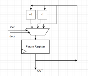
From here, the block diagram for the delay component was:
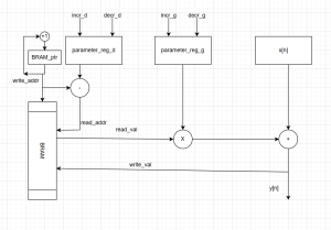
The multiplication operation was implemented using an on-chip DSP slice, since I assumed that any custom implementation would take far longer to create a circuit around the same speed. The DE10-Standard FPGA also contains double-ported BRAM, meaning that the concurrent read/write operation necessary for this component can be natively supported. Next week, I hope to implement the RTL for the IIR and FIR components.
Jose’s Status Report for 03/07
I spent most of the week working on testing out and debugging the FPGA interface with the built-in codec (apart from working on the design report with my team). There was some time spent getting caught up again on Quartus’ features and tools, since most of my recent work had been through the use of Vivado. Once that was over, I set up all the pin assignments as required for the I2C and I2S interface, being left with the following physical debugging setup:

The most significant 4 LEDs are meant to represent the state for the main I2C setup FSM, which is a four bit value. The next four are of the same type, but they show the states for the internal I2C protocol FSM (just to be clear, the main I2C setup FSM sends out the write commands while the internal one manages the actual ack handling, SDA pulling, etc.). Finally, the last two LEDs are meant to represent the error signal (in the case that something with the protocol went wrong) and the done_sending signal (which indicates that data finished sending). I spent a while trying to debug an issue with the overall setup FSM, wherein I was setting the “send_data” signal to high for only one clock cycle. This caused issues with the protocol FSM, because I have it set up so that it sends out data and manipulates the clock at a rate of 250 Khz (in the case of the 50Mhz clock, I’d be manipulating state once every 250 ticks). This caused “send_data” to not be perceived by the protocol FSM, and leave the setup FSM in its first state as the protocol wouldn’t be activated. Once I modified the setup FSM, the FPGA’s LED representing “done_setup” lit up. While this was the main factor for identifying that the system was functioning properly, it also helped that the CODEC began outputting audio from the line out port, as seen in the video below:
https://youtube.com/shorts/HG-n8KKO8Xg?feature=share
While I have a simple square wave being outputted, my plan for the next week is to more thoroughly test the audio CODEC and investigate how to extract its output for signal comparison in MATLAB. Specifically, I’ll try testing different types of audio output to see if there is variance with the output (that is, I’m not just outputting random noise). I’ll also look into using Quartus IP for generating a 12.288MHz clock utilizing a PLL (since right now my approach could most definitely be fine-tuned). This is in line with the schedule, and no catching up is needed.
Team Status Report for 03/07
So far, no changes to our schedule have been made nor new risks have been posed. Because the audio output system interface was set up with a square wave (or noise, it’ll be properly tested this following week), there is now a bridge into getting different signals outputted (and proper testing of waveform/filters). Right now, getting the CODEC functioning properly is the main priority and risk, but at the current pace we’re at it does not seem to pose too much of a challenge. Apart from working on the design report as a team, that is the main progress of the week. The video for the FPGA outputting audio can be seen in Jose’s status report.
How will our project meet the specific needs with regard to the following?
NOTE: A was written by Jose, B was written by Mihail, and C was written by Jose.
A (global factors):
In contrast to software synthesizers, hardware synthesizers are meant to be used without external computers or software. This means that FPGSZR can become much more accessible globally, since anyone can use it if they have a computer, no computer, or a variety of musical equipment. In other words, this means that people of all backgrounds can create music on a global scale (no matter the background, anyone can use the tool). Thanks to the product’s ease of use and low cost, classrooms can integrate them into their coursework and have students learn about the fundamentals of digital synthesis. Moreover, FPGSRZ’s standalone nature avoids any stalling thanks to external tools or instruments. That means that the system is reliable in many sorts of situations in which constant operation is required (live performances, classrooms, etc.). Altogether, these factors identify how FPGSRZ can affect the entire world in a positive manner, not just being limited to the city of Pittsburgh or one cultural group.
B (cultural factors):
This project carries significant cultural impact due to the fact that it is meant to be a cheaper alternative to a musical instrument. Music is a key part of cultural expression, and access to instruments can affect who is able to participate in music production and creative communities. Traditional hardware synthesizers can cost hundreds of dollars, which may limit access for students, hobbyists, or musicians, especially those from lower income backgrounds. By designing a lower-cost FPGA synthesizer that still supports standard MIDI keyboards, polyphonic playback, and a wide range of effects such as filtering, reverb, distortion, and multi-band compression, our system helps lower the barrier to entry for electronic music creation. This accessibility allows individuals from diverse cultural and economic backgrounds to experiment with music creation and express their own musical traditions or styles. Additionally, because the system is modular and based on widely used standards such as MIDI, it can integrate with a variety of instruments and musical workflows used across different communities, supporting a more inclusive range of musical practices.
C (environmental factors):
This project carries a significant benefit to the environment thanks to the fact that we are using an FPGA as the center of computation. Traditional hardware synthesizers carry a multitude of specially made components that cannot be reused elsewhere (think integrated circuits and the like). When the devices serve their purpose, people are inclined to then throw it out and create technological waste. If disposed of improperly (which can occur often), toxic substances like lead and cadmium can be released. Because of FPGA’s reprogrammable nature, the user can reprogram its internals to serve other uses when they do not need to use a synthesizer anymore. Essentially, they can reuse the component and avoid the need of throwing anything out and creating e-waste. To us, this is the most significant environmental benefit that comes about from our project.
Kaloyan’s Status Report for 03/07
This week, I worked on developing the RTL for the ADSR and the wavetable sampling. I also worked on the design report, and thought through the implementation details for various subsystems in the RTL that I was working on. This involved the design of the ADSR RTL and FSM. Although it was simple, the design helped guide my implementation process. I’ve attached a diagram of the FSM below, which I used when implementing my design.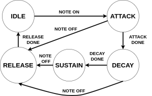
These attack, decay, sustain, and release times will eventually be set by the user, and configured in order to provide a dynamic filter and amplitude response. Additionally, I worked on understanding BLEP (Band-Limited Step Functions) to correctly interpolate sounds when working with signals like square, saw, and triangle. The use of BLEP allows the sound to avoid infinite harmonics and harsh frequencies, creating a continuous change rather than a sudden discontinuous jump. Through this, we are able to preserve the harmonics of the sound while avoiding harsh frequencies, at the cost of minimal additional memory usage and simple digital logic.
Kaloyan’s Status Report for 02/21
This week, I worked on implementing the basic waveforms in RTL. This process involves describing the 4 basic waves we set out to provide to the user, sine, square, saw, and triangle, and then allowing the user to play these notes out through the MIDI keyboard. In order to do this, I am using a LUT for the sine wave values. I generated this LUT using python, and then stored the values in BRAM. Then, I use a phase accumulator to index into the LUT table and play out the corresponding amplitude for that phase index. For playing different frequencies (AKA pitches), we can vary how much we increment the phase in every clock cycle. I have implemented this partially in RTL, but am now planning on verifying it by capturing the output and then comparing it with the sine wave we would expect for a given note. The next step will be to try to play the audio out of the CODEC, to verify that the generation is happening smoothly. Additionally, I will also work on the square, saw, and triangle wave, which will need interpolation in order to properly play and avoid harsh aliasing errors.
Team Status Report for 02/21
For this week, no particular changes were made to the overall design structure. Although we’ve spent the week working on specific portions of the design, nothing has caused the aforementioned or a change in our schedule. The biggest risk so far has to do with the audio codec, since it’ll be the main mechanism for testing our signal generation/effects in every possible way. If not finished on time (for this week), then the plan would be to spend time on spring break remediating any issues with it. This’d involve debugging through simulation and waveform analysis, checking with oscilloscopes as well.