Justin Bell Status Report 2/21/26

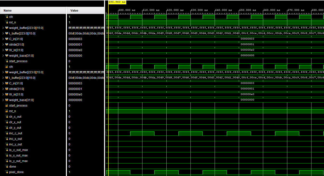
This week was pretty much all about getting the convolution unit to actually do what it is supposed to do. A big chunk of the time went into debugging the hardware itself, making sure the FSM handles chunk-based MAC accumulation correctly, the pipeline latency between when the last MAC fires and when pixel_done asserts is actually valid, and that the buffer addressing is not silently truncating and causing aliasing issues. The whole chunked approach where you tile across K x K x C_in inputs spread across 64 MACs per cycle is solid in theory but has a lot of edge cases to shake out especially around accumulator clear timing and handoffs between output pixels.

On the software side you put together a numpy golden reference script that runs both 3×3 and 1×1 INT8 convolutions from scratch and dumps hex outputs you can feed directly into your testbench. The idea is to have a clean bit-accurate ground truth to compare against hardware readback so you can actually say these match instead of just eyeballing things. The plan is to eventually extend that into a full pytorch-backed reference flow where you can pull the actual YOLOv3-Tiny weight tensors and run them through the same pipeline so verification stays meaningful as the design matures.

The bigger picture goal tying all this together is getting every piece of the CONV2D pipeline working as a unit, not just the MAC array in isolation but the whole chain with bias add, requantization, leaky ReLU, and eventually maxpool feeding into the next layer.

Team status report for 2/21/26

Significant risk: Localization


During the design presentation, we received feedback about potential issues with localization when strictly using the odometry sensor. We believe that part of this was due to confusion about how our sensor works, as the main issue brought up was how optical sensors can be inaccurate. We tried to explain that the odometry sensor uses both an optical sensor and an IMU and cross-references readings from both to get more accurate data than either one individually. 


In spite of what we see as a misunderstanding of how the sensor works, it does raise a good point about redundancy for localization. Our odometry sensor is rated to be less than 1% inaccurate when calibrated for the surface it is going to be used on. However, the surfaces of CMU buildings vary, and because we have not tested the variance between them, we do not know if the sensor would maintain a similar level of accuracy when traversing different parts of a single building. Even if it maintain its sub-1% inaccuracy on all surfaces, any inaccuracy at all leads to drift as the robot continues to travel. For resets of paths, we had planned on creating an identifiable “reset point” that the robot knows to reset its localization drift.


To address the concern about drift, we can expand on this idea of reset points through the creation of “landmarks” along the paths that the robot can potentially take, resulting in multiple points of recalibration and error reset during any given path. Three forms of markers that we have explored are QR codes, ArUco markets and AprilTags, all of which are systems of black and white squares that encode information based on the pattern, allowing the robot to distinguish between them. In addition, their standardization means that the angles of their edges relative to the camera and each other can be used to identify distance.


Schedule change: Due to an unforseen situation preventing Paul from properly working this week, he is doing last week’s work this week, and this week’s work during spring break.


Paul Wright Status Report for 2/21/26

What I have personally accomplished this week/schedule changes:

To be completely honest, I have done little this week outside of KR260 setup and working with Sean and Justin for localization alternatives. You can see his post for more about those alternatives. Over the past week, I have had to deal with an emergency in my personal life that has taken me away from anything CMU. It is now fully resolved, and I expect to get back on track. I communicated this with my teammates, and I am thankful for their recognition of and willingness to adjust to this disruption. I plan to spend significant time over spring break to make up for this week of lost work.

What deliverables to complete in the next week:

Complete KR260 setup and necessary installations.

Complete design report alongside teammates.

Continue with software setup and coding for odometry.

Sean Johnson Status Report for 2/21/26

What did you personally accomplish this week on the project?

This week I focused on investigating alternative localization approaches after our professor had skepticism about relying solely on the optical flow sensor (PAA5160) for accurate navigation. We received feedback that odometry localization may not be reliable enough for our accuracy requirements. The main alternative I explored was marker systems, specifically ArUco markers, AprilTags, and QR codes that could be placed at known locations throughout the building hallway. The idea is that our existing camera could detect these markers and use them to reset or correct position estimates during navigation, compensating for any drift accumulated by the optical flow sensor.

I evaluated several sensor fusion architectures that could combine multiple localization inputs. The most promising approach uses the odometry sensor for continuous tracking between landmarks and visual fiducial markers for periodic position correction. This hybrid system would leverage the strengths of each component while mitigating their individual weaknesses. For implementation I researched how the OpenCV ArUco detection library could integrate with our existing camera hardware and CV pipeline. A hybrid approach using optical odometry for continuous tracking with periodic visual landmark corrections could achieve our position error requirements while being significantly more robust than odometry alone. ArUco markers can be detected in real time with our YOLOv3-tiny human detection without creating a significant performance bottleneck.

Is your progress on schedule or behind?

According to our Gantt chart, Task 3.1 should be complete by the end of Week 2. While I’ve made progress researching the optical sensor and understanding its capabilities, the professor’s feedback revealed that we need a different solution. This puts me a few days behind on finalizing our localization approach since we now need to integrate additional components we hadn’t initially budgeted time for. Our team will make a decision on our approach very soon, whether that’s pure odometry or odometry with visual landmarks.

What deliverables do you hope to complete in the next week?

My primary deliverable is getting the optical flow sensor operational with working code. I need to write the interface code to communicate with the PAA5160 sensor and pull X/Y displacement readings. This will be implemented in Python interfacing through the Arduino. Once I have raw sensor data coming through, I’ll implement a basic position tracking algorithm that integrates the displacement values over time to estimate the robot’s current position.

Paul Wright Status Report

What I personally accomplished this week:


This week, I continued work with Justin around the robotics kit and chassis, where we decided on the Hiwonder Tank Chassis Kit. After we settled on the kit, I  began looking at first and 3rd party projects that used the kit. My math for the battery size needed lines up with what they needed for 1 hour of operation: 2200mah. 

Last week’s outstanding deliverable was finding a battery for the vehicle. I have finished that. We will be using 2 separate batteries: a 7.4V one for the Motor and a 12V one for the KR260 and Arduino. I also added an H-bridge to the design, which is a rather embarrassing oversight.

With the completed parts list, I began on the CAD model of the physical design. I hoped to be complete with it to remain on schedule, but the chassis has a surprisingly sparse amount of 3-dimensional information. A lot more additional work has had to be done to be able to properly represent it.

I also spent time learning about the KR260’s software stack and how we are going to integrate everything. I have no experience with ROS2, and am trying to get myself up to speed. I found these to be very useful for that.

https://youtu.be/0aPbWsyENA8?si=MZzz1h8PobvCQmXA

https://youtu.be/Se5pvRlTX8s?si=UA6VJxq1sKDpnBYE

Finally, I spent time learning about setup and configuration of our odometry sensor and how to use the data it gives so that we can properly integrate it into our whole system.


Progress relative to schedule:

Slightly behind schedule in terms of completion of CAD model of system, but just by a small amount. 


Deliverables for next week:

  1. Begin setup of KR260 to match Justin’s once we get it from ECE inventory.
  2. Complete CAD design.
  3. Order parts
  4. Continue with software setup and coding for odometry.

Team Status Report for 2/14/26


Our project has received a change in use case upon further discussion with faculty and evaluation of parts within our budget. We are switching to delivery from last-mile delivery to delivery of small objects within a building. This removes the need to read and identify signs, and reduces the number of potential obstacles. In addition, the more consistent lighting and surfaces will help our camera and odometry system to function better. 

Last week, we brought up the depth-sensing cameras. We were notified that they were mistakenly marked as available on the inventory sheet, so we will not be going farther down that route and will instead be continuing with bounding boxes.

Risk 1:  With the RTL pipeline this week a risk that can happen is that right after the last chunk is said to be done on a convolutional layer the next chunk can get processed. This could lead to the Multipliers and adder tree not being done and starting another layer messing up the actual accumulated value.

Risk 2: Proper balance of vehicle with multiple batteries: We identified the need for multiple batteries for the KR260, motor systems and arduino. With limited space on the vehicle chassis, we need to align them so that we do not have an unbalanced vehicle that, while functional, will make accurate movement and turning more difficult to implement.


Part A: Written by Paul

When considering public health and safety in our use case and design, our primary focus is not to be a hazard to people who go through hallways. This is emphasized in two of our primary design requirements of being able to identify and change navigation when a person is within 2 meters under 50ms and to be able to stop within 0.5m. The robot needs to react to and navigate around people quickly enough that the person will not have to alter their path. This is especially important for those with movement impairments or sensory disabilities. For those without them, a robot getting in the way just means stepping out of the way or slightly changing tour path, an inconvenience that rarely would cause a real safety hazard. However, for those with impairments, quickly changing paths or stopping is a much taller order that can risk their safety, and for those with sensory impairments, they may only detect the vehicle as it is crashing into them.  


Aside from our design goals, our focus on public health and safety is exemplified in our curation of training data. We are placing special focus on using data that includes those who are holding objects that obscure parts of them and who are in wheelchairs. Focusing on those with impairments and disabilities also helps those who do not have them, as they can temporarily have them. Consider a maintenance worker who is holding a large box in front of them. They are partially vision impaired at that time, and should not have to worry about a small robotic car that is out of their field of vision.


Part B: Written by Sean

Our autonomous indoor delivery robot is designed with careful consideration of social factors, particularly its operation in shared indoor pedestrian spaces where diverse social groups are present. By prioritizing people detection and obstacle avoidance, our system respects the fundamental social principle that indoor corridors, lobbies, and pathways are primarily human spaces. Users including children, elderly individuals, people with disabilities, and those carrying packages or using mobility aids should feel safe and comfortable around our product. Our focus is on maintaining appropriate distance from pedestrians and stopping when people are detected which is critical for settings like university campuses, hospitals, office buildings, and residential complexes. Predictable behavior addresses social concerns about robots operating in confined spaces where surprise encounters could cause discomfort particularly among vulnerable populations like elderly residents or young children. Our design acknowledges the importance of prioritizing human presence over delivery efficiency. Our solution aims to gain community acceptance by operating as a considerate “neighbor” rather than prioritizing speed. 


Part C:  Written by Justin

When considering economic factors, our product is designed to be a practical and efficient solution for real time video processing on low power hardware. The KR260 based computer vision system delivers fast inference while consuming significantly less power than a traditional GPU and providing far more capability than a typical microcontroller. This balance between performance and energy efficiency reduces operational costs through lower power consumption, longer battery life, and reduced cooling requirements. For delivery robots that must react quickly to obstacles, this efficiency translates directly into both safety improvements and long term cost savings.

From a production and distribution standpoint, the system relies primarily on commercially available, off the shelf components rather than custom manufactured hardware. This reduces upfront development costs, minimizes supply chain risk, and allows for easier scaling. The main bottleneck would likely be shipping and lead times rather than specialized fabrication. Because the design is modular, components can be replaced individually, lowering maintenance costs and extending product lifespan.

Sean Johnson Status Report for 2/14/26

What I personally accomplished this week:

This week I focused on refining our position tracking approach with the PAA5160E1 optical sensor. I discovered that the sensor uses I2C communication, not SPI as initially thought. This simplifies our integration, the sensor will connect to the Arduino rather than directly to the FPGA, since it has an onboard STM32 microcontroller that outputs processed position data over I2C. I reviewed the SparkFun documentation and Arduino library for the PAA5160E1 to understand the integration workflow. The sensor provides X/Y displacement values that we can accumulate into absolute position. I studied how to read position data via I2C on Arduino and forward it to the KR260 over serial communication for use in navigation decisions.

I also researched how to calibrate the sensor and handle edge cases like sensor drift and surface compatibility. The sensor requires mounting 10-27mm above the tracking surface and works best on hard floors, which matches our indoor demo environment.

I continued learning ROS2, focusing on how position data flows through navigation nodes and how to structure communication between the Arduino, handling sensors/motors, and KR260.

I coordinated with Paul on mounting requirements for the optical sensor on our chassis design.

Progress relative to schedule:

On schedule. This week’s work on optical sensor integration planning aligns with Gantt chart task 3.1 (optical sensor) and 3.4 (position tracking).

Deliverables for next week:

  • Complete integration plan for PAA5160E1. Arduino I2C interface and serial communication to KR260
  • Begin testing basic I2C communication with Arduino if sensor arrives
  • Define data format for position updates sent from Arduino to KR260
  • Continue ROS2 learning focused on position/odometry message types

Justin Bell Status Report for 2/14/26

This week I revisited the convolutional layer in my YOLOv3-tiny hardware implementation and realized that the original conv_2d module was not properly parametrizable for the full network. It was too tightly coupled to a specific layer configuration, particularly around fixed kernel size, channel count, and accumulation structure. That meant it would not scale cleanly across the different convolutional layers in YOLOv3-tiny.

I restructured the conv_2d module to be fully parameter driven. I introduced parameters for kernel size, number of input channels, number of output channels, and maximum supported input channels. The data path is now dimensioned based on these parameters rather than hard-coded constants. Internally, I redesigned the MAC array so that instead of supporting only 27 multipliers tied to a specific 3x3x3 style structure, it now instantiates 64 parallel multipliers. This gives more parallelism and aligns better with a scalable channel processing strategy.

I also added a dedicated accumulator inside the MAC unit. Previously, partial sums were not handled in a way that would scale across large input channel counts. Now, each output feature map element accumulates products across all input channels in a structured way. The accumulator supports up to 1024 input channels. For layers that have fewer than 1024 input channels, I zero-pad the unused inputs so that the accumulation loop and hardware structure remain consistent. This allows the same hardware structure to be reused across layers with different channel depths without redesigning the control logic.

Additionally, I updated the control logic so the same conv_2d module can handle both 1×1 and 3×3 convolutions. The kernel size parameter determines how the sliding window and multiply scheduling behave. The internal indexing and loop bounds now depend on the parameterized kernel size and channel counts, so the same module can be reused across all convolutional layers in YOLOv3-tiny.

Right now I am validating all 1×1 and 3×3 MAC operations in simulation without quantization or post processing. The goal is to ensure that the core multiply accumulate behavior matches a reference implementation before introducing fixed point quantization and activation functions.

On the project direction side, based on feedback, we decided to pivot away from traffic sign detection and instead focus on making the robot more careful around people. This allows us to use the standard COCO dataset with YOLOv3-tiny instead of building and training a custom dataset. That reduces training overhead and lets us focus on hardware deployment. I will still need to properly quantize the pretrained model for the FPGA board, but this avoids retraining from scratch.

Goals for next week:

  • Have most of the model working functionally in simulation

  • Implement a Python reference version so I can verify outputs and prepare for weight loading

  • Purchase the remaining hardware components

  • Prepare slides and demos for the presentation

Paul Wright Status Report for 2/7/26

What I personally accomplished this week:

This week, I coordinated with justin about the robotics kit/chassis, optical sensor solution, and delved farther into potential depth implementations. As Justin’s report said, we have looked at multiple different chassis.  Our current frontrunner is linked below, with our only potential reason for using it either being power consumption or mounting other components, which require more work on my end. I have yet to find any evidence that treads would cause enough vibrations to disrupt proper odometry.

Hiwonder Tank Car Chassis Kit Shock Absorbing Robot with DC Geared Motor for Arduino/ Raspberry Pi/ Jetson Nano DIY Robotic Car Learning Kit (Black)

We also decided on our optical sensor solution, the Sparkfun PAA5160E1. Below is a brief showcase of it. After reading datasheets and looking at projects that have used it, I believe that it will work for our positioning needs, given that we are using flat surfaces.

As the ECE parts list opened up, I identified potential alternate solutions for distance estimation. The most desirable one is the Intel Realsense Depth Camera D455. It would provide much more accurate depth than our currently planned bounding box estimation. However, we are worried about CPU overhead, as it would mean that both a camera feed and depth map are being input, so this would only be implemented if we have the overhead.  Below is a video that I found helpful for understanding how we would use it.

The second potential depth-sensing camera is the eYs3D Stereo Camera – EX8036. It appears to be a slightly worse option than the Realsense in terms of actual hardware and ease of integration.

Finally, a couple of hours were dedicated to rehearsing the Proposal Presentation.

Progress relative to schedule:

I feel that I am on schedule for everything except for deciding on our battery to meet our design requirement of the system lasting for more than 30 minutes. I am behind on this and expect to address this by finishing it on 2/8/26.

Deliverables for next week:

1.Finish finding battery for vehicle.

2. Investigate any potential issues with part selections to confirm choices.

3. Create a basic CAD model of entire vehicle

4. Begin preliminary work of software construction for path creation.

Justin Bell Status Report 2/7/2026

I’ve got the CONV 3×3 implementation working with INT8, which is a solid milestone for the hardware pipeline and gets us closer to the final architecture we need for real-time inference. Right now I’m focusing on making the whole thing parametizable so we can easily adjust configurations without having to rewrite a bunch of code every time we want to change kernel sizes, data widths, or number of channels. It’s coming along pretty well and the basic structure is there, but there’s still some refactoring to do to make it clean and flexible enough to handle different use cases down the line. The goal is to have something that’s modular enough that we can swap in different layer configurations without breaking everything, which will be really helpful once we start optimizing for different parts of the YOLO network.

On the model side, I’ve been spending most of my time training with traffic signs datasets to get the detector tuned properly for our specific application and use case. The goal is to get good accuracy on sign detection specifically since that’s what we’re targeting for the real-time demo on the Kria board, and we want to make sure it actually works well in real-world conditions.

I’m also deep in the research phase for quantization strategies, which is pretty critical for getting this running efficiently on the FPGA without sacrificing too much accuracy. Trying to figure out the best approach to get from floating point weights and activations down to INT8 without totally tanking the accuracy or introducing too much quantization error that would mess up our detection performance. There are a few different techniques I’m looking into – post-training quantization which is simpler but might lose more accuracy, quantization-aware training which should preserve accuracy better but takes more time, and some hybrid approaches that try to get the best of both worlds. I’m still working through the tradeoffs and running experiments to figure out what makes the most sense for our FPGA implementation and performance requirements, especially considering we need to hit that sub-30ms inference latency target while maintaining reasonable detection accuracy on traffic signs.