
This week, I continued working on figuring out how we’re going to use Bluetooth in Remigotchi’s firmware. I built a testbench that implements BLE Serial, where you can stream bytes from one device to another once they are connected via BLE. This simplifies the firmware that we need to write by a lot. Instead of us directly manipulating GATT tables and defining our own standard of communication, we can treat it like something closer to just a serial stream. That being said, we will probably still have to handle things like our own error detection/correction and data packet structure. I also began testing our custom PCB that we received earlier this week. BLE works! I can get a serial stream to and from it via USB-C. The power seems functional enough. The charger IC gets up to 75 deg C while charging, which is mildly concerning, but potentially still within spec, so I’ll have to check on that. I tested the passive buzzer and realized that it’s unnaturally quiet. I measured the peak-to-peak voltage and eventually looked back at the datasheet and realized I wired the NMOS driver on the wrong side of the buzzer. It should be pulling the buzzer down, and the NMOS source has a stable “ground” so that the gate-source voltage is definitively 3.3V or 0V when being driven by the GPIO pin. To fix this, I’ll de-solder the buzzer from the PCB with a hot air gun, attach jumper wires to it, and use a breadboard NMOS to wire it up correctly and see if that works. Below is a picture of what my schematic is on the left, compared to the recommended application from the datasheet on the right.
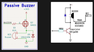
I’m a week or two behind schedule because we underestimated how long it would take for the PCB to get here. According to our original schedule, I think I would be either ordering or testing the second PCB by now. However, I still need to confirm with Italia whether or not the pinouts for the RFID reader and LCD screen work. To catch up, I’ll spend extra time next week testing the PCB.
Deliverables I want to have done next week are: working breadboard model of adjusted passive buzzer circuit, testbench firmware proving that the micro SD card slot works, testbench firmware proving that getting the time of day via GPS works, and testbench firmware proving that the RFID reader works.