What did you personally accomplish this week on the project? Give files or photos that demonstrate your progress. Prove to the reader that you put sufficient effort into the project over the course of the week (12+ hours).
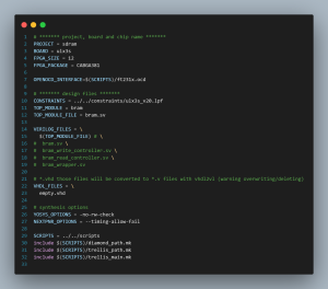
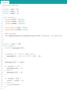
This week has been mostly trying to debug my JPEG decoder implementation. As of right now, the JPEG decoder flashed on the FPGA doesn’t actually produce any results. I’m not entirely sure if this is because there’s an issue in the way the Arduino is sending the FPGA the JPEG bit stream or if there’s some inherent bug with the JPEG decoder.
Is your progress on schedule or behind? If you are behind, what actions will be
taken to catch up to the project schedule?
I’m a bit behind on the JPEG decoder itself but luckily this is the only thing that’s a bit behind. I plan on continuing to do some testing, most likely start with preloading the image onto the FPGA and seeing if it decodes it properly.
What deliverables do you hope to complete in the next week?
I plan on hopefully getting everything sorted out with the JPEG decoder next week.
What did you personally accomplish this week on the project? Give files or photos that demonstrate your progress. Prove to the reader that you put sufficient effort into the project over the course of the week (12+ hours).
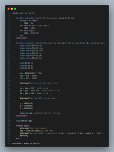
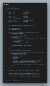
This week was mostly spent into integrating the JPEG decoder into the pipeline and debugging issues that arose. Another big piece of the puzzle that I had missed was converting the decoded YCbCr output of the JPEG pipeline back into RGB.
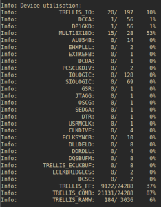
This was fairly tricky to implement as this required a lot of floating point computation. I had to work on pipelining the design so that I could actually fit the design onto the FPGA. There are about 28 18×18 multipliers available on the FPGA, each pixel required about 4 of the 18×18 multipliers so I had to make sure to find a way to sufficiently parallelize/sequentially the decoding to use the multipliers the most appropriately.
Is your progress on schedule or behind? If you are behind, what actions will be
taken to catch up to the project schedule?
As of right now, I am on schedule so I’m not worried about my progress. Though it will be a little tight to get everything in for the interim demo.
What deliverables do you hope to complete in the next week?
I plan on hopefully getting everything sorted out for the interim demo.
Verification Test
Luckily, by doing almost everything in hardware, most of the verification has already taken place. This means in terms of things like how stable is the HDMI output to the display and the rate at which the JPEG decoder operates.
The HDMI frame rate can be monitored by an external display. The display will be able to display the input frame rate and this can be monitored for an hour to ensure that it stays at a stable 60fps. A success here would be marked by not missing any frames during this time.
The JPEG decoding rate is solely determined by how the design is pipelined and the clock speed of it. Currently, the 25MHz clock that the JPEG decoder is running at is more than sufficient to meet the effective 60fps (6 streams @ 10fps) required for the project.