Aidan’s Status Report for Apr. 8, 2023

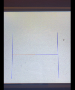
I spent the first half of this week working on getting our interim demo ready for wednesday. The first thing that Neha and I focused on was integrating the LED and LCD displays with the output of the pathfinding code. Originally, we were able to display directions, but after reformatting our code to import the functions that we used, we were able to create a file to run our loop function that could utilize these functions. After integrating, we could specify a path, and the node would show the direction to go (Left, right, up, down) on the LEDs, as well as the path to follow on the LCD display.

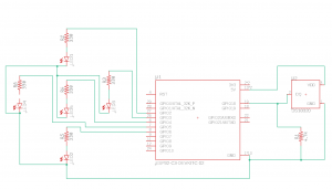
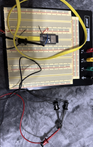
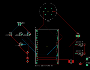
The other main thing that I worked on this week was the pcb design. A big part of this was adding the backup battery circuit to our schematic, which is something that Neha and I worked on. After this, I also cleaned up the LED circuitry because I found that I could reduce the number of resistors needed by running the LEDs through one resistor to ground instead of each LED having its own resistor. However, Neha and I did find out that we would not be able to do this for the red and green LEDs together. We attempted to do this on our breadboard and got errors when uploading to our ESP32. I am assuming this is because of the different forward voltages of the LEDs. After making these changes I created a board layout by moving all of the components onto a board in Eagle and using the autorouter. The autorouter returned a board layout that used two layers. I was initially hoping that we would be able to do it on one layer, so I spent some time looking into this and seeing if there are any changes I can make to only use 1 layer.

One of the tests that I am planning on running is testing how long our system can run on the battery supply. For this I want to create a circuit so that I can test all of the components at the same time. Once I can do this, I will see if our system can run for 24 hours straight. 24 hours was our design requirement. To begin this task I will collect all of the software that I need to run the individual pieces. I am hoping to accomplish this this coming week. Another test that I want to conduct is the testing of the system as a whole. Once Neha, Jason, and I’s code is integrated, I think we should begin testing by holding a flame to the nodes and looking for the correct output on our LED and LCD displays. Also, as I mentioned previously, I feel that we need to test our system by wiring it up the same way that our PCB design specifies. After this we will test to make sure that all of the components are working correctly to ensure that our PCB design is valid on wall power and battery power.

This week, one of the tasks that I want to complete is verifying our PCB layout. With the exception of the battery charging circuit, we have tested the individual components separately, but together. This is something that I for sure want to accomplish before we begin manufacturing the final PCBs. This way we can also fine tune resistance values and hole sizes to prevent issues we may have further down the road with our design. Another thing that I wish to accomplish is to integrate the display code with Jasons pathfinding code. Currently we are able to take a path, so I do not think that there will be too much work to integrate these systems. One other taks I want to finish this week is to find a floor plan on campus that we will use to create our video demo. As some of our code will be hardcoded to match the building specifically, having the building in mind may save us some time.

Currently I believe that I am on schedule. There were some changes that we made to our schedule this week, but I believe we covered these changes in our interim demo. Some of these included changes for the PCB because we were thinking that we may make them ourselves. However, I am still on track to finish my tasks on time, according to our new schedule.

Neha’s Status Report for Apr. 8, 2023

This week we spent some time working on integration in preparation for our interim demo. We worked on adding to our PCB design as well as coding the LEDs to work in conjunction with the displays based on some hard coded paths and being able to pick the corresponding direction and highlight its matching path. I have also been working on finding the threshold for the smoke sensor that we will use for our fire detection but am still running into issues where different sources have different values but I am determined to get past this block this upcoming week to even see if we are getting accurate smoke readings based on how we wire them up.

One particular step that I am struggling with is figuring out the best plan of action for our PCB design. While Aidan has also been working on our design, we know that this can be applied to the machines in techspark that we had visited last week. However, there does not seem to be resources available besides youtube videos and manuals which have been our research for now. I have also been communicating with Quinn about possible resources as I had mentioned wanting to do in my last status report, and he had mentioned two embedded TAs but after messaging they actually only have experience assembling already fabricating PCBs. Quinn also recommended using JLCPCB in parallel so at least we have a way of getting these PCBs especially after realizing we might be having a 2 layer board. After our interim demo, we also brought up these concerns with Professor Mukherjee and Kaashvi to which we were recommended to reach out to a student of Professor Carley, Brandon Gonzalez, about our options there as he has done research in the area so I plan on reaching out quickly. 

For the components that I am working on, I have a testing mechanism that relates to each individual circuit. For example, for the smoke and temperature sensors we have created a threshold of fire in proximity to the sensor itself and we will be able to detect if our node senses this fire or not. For the sake of testing, we would be using a lighter or a candle. For the LEDs circuits, Aidan and I have already tested being able to input different North, East, South, West directions and have the LEDs correspond to those directions. We also tested hardcoding a path based on four nodes and three edges allowing us to output a specified path. This was also highlighted in our display which shows some of our initial integration between working with the ESP32 to both the individual LEDs and also the display. In regards to testing the actual PCBs, that would come with assembling them when they come as we want to make sure that based on our Eagle file that we can replicate the circuits that we have already breadboarded. My components relate to the fire detection use case requirement where we specified that 95% of fires are detected and in order to do so one way to go about it is as we keep testing our nodes by moving a flame towards the sensors, we want to ensure that 95% of the time they are detecting the fire, which currently doesn’t seem to be an issue as we have both temperature and smokes sensors. The other design requirement that my components relate to is the use case requirement that we want to show directions in less than 100s after fire detection. Here this integrated the pathfinding computation with downloading time and the time to display instructions so while this combines separate subcomponents, ideally when testing we could time this to see if we are within our limits.

In the upcoming week, I want to figure out how to get precise smoke sensor readings, wrap up the PCB design and either act on a response from Brandon or send out the PCB design to be fabricated in parallel as well as finalize the rechargeable battery circuit to be able to order the hardware necessary (diodes, resistors, battery holders) as well as figure out how that plays into our PCB design. Furthermore, we would like to continue more steps toward integration especially between pathfinding on Jason’s end so that we can make progress away from just hardcoding paths but paths that actually correspond to smoke and temperature data. With regards to the Gantt chart, we updated it with smaller tasks that need to be done to reach our bigger goals and most notably, we pushed back the PCB component of design and fabrication. With these new edits I am mostly on schedule especially when prioritizing the smoke threshold and using that in conjunction with the temperature sensors so I can test them simultaneously. 

Aidan’s Status Report for Apr. 1, 2023

This week, I was a little busy because of two midterms that I had, so I was not able to get as much done as I had hoped, but I was able to make some good progress. First, during class, Neha and I were able to get the smoke sensors working. However, one issue with the setup that we had is that the output was unusable. We tried adjusting this by putting a resistor on the output pin, but this did not seem to help too much. After doing some research on this part, we found that they are often shipped already attached to a PCB. When looking at this PCB, we could see that the sensitivity of the device was set through a potentiometer. I think that using a potentiometer to fine tune our resistance would be a good idea for us as well. Once we have this dialed in, we can decide on a resistor to use for our final PCBs.

For the PCB design, I was still unable to find a library for the MQ2 sensors that we are using. Because of this, I decided that I would have to create my own part. This consisted of 3 stages. First, I had to create a footprint for the device that specified the location of the pads. For this I had to do some mild trigonometry based on the specifications in the datasheet, as these were given in polar coordinates, but Eagle takes rectangular coordinates. Then, I had to create the symbol which just consisted of me creating the shape that would appear on the schematic. Lastly, I had to make the device, connecting the pins of the symbol to the pads of the footprint. After all of this, I was able to add my part to the schematic that I have been working on. I learned a lot about Eagle from this, and I think that this is going to help us as we finish up our PCB design. I was going to add a picture, but I couldn’t get WordPress to accept it, even when I reduced the size.

Lastly, I also met with Jason this week to begin integrating our pathfinding and LCD display code. However, not too long after we started, we realized that we would need to make some changes to the code before they could be integrated. The LCD code was fairly easy to modify, but the pathfinding code will need a few changes before it can be integrated. 

Currently, I am a little behind schedule on the PCB design. Creating the custom smoke detector was one of my goals for this week, and I did complete that, but we had hoped to have this finalized by last week. However, this week, we spent some time looking into alternative fabrication methods, and I believe that by making the PCBs ourselves, we will be able to save some time and money. This is how I think that we can make up the time in our schedule, as we leave a couple weeks in our schedule for manufacturing and delivery. We are also behind in our pathfinding integration and testing, but my schedule this next week is not very busy, so I believe that Jason and I will be able to spend a good amount of time and hopefully finish some of this before the interim demo.

Next week, I am hoping to create a final PCB design that includes all of our components. Including the batteries. I am also hoping to get the display integrated with the pathfinding code. Currently, I have put a pause on the distributed pathfinding, as Jason and I would like to get a version working before we start on the other version. I would also like to look into integrating communication with pathfinding. The one other thing that I need to do is look at battery holders for our AA batteries and pick some to order or 3D print.

Team B8 – FireEscape’s Status Report for Apr. 1, 2023

At the moment, we realized that after our weekly meeting with Professor Mukherjee and Kaashvi that we are in a better place than we thought for our interim demo. We, however, don’t want to fall behind so we are aiming to keep the efforts on integration high as we keep progressing toward and beyond our interim demo as we still stand by the fact that it will be difficult to combine each individual demo. Currently, we feel that the most significant risk would be the fact that our batteries have not arrived yet. Our rechargeable battery circuit is a part of each individual node and we need to ensure that our node works as a whole in terms of power draw and designing appropriately fitting PCBs. Regarding the Eagle design, we can just do the rest of the design without the batteries for now and then add it in, but ideally, we could get it all done as soon as possible. 

Another risk could be the making of our own PCBs as we mentioned in our last report. After our weekly meeting, we went to TechSpark to check out the machines that will print them on copper sheets. We have a copy of the manual and we know that we still need to create an Eagle file, but it would be great to get in touch with people who have used it as we are very new to it and will most likely have a lot of questions. We need to figure out very soon whether this approach of making our own PCBs is going to work for us, as the window of time for ordering a PCB from one of the standard manufacturers is running out quickly.

One other risk that we ran into is that our code is written to run on its own, not to be integrated with other code. This will just require some more time on our part to ensure that the code will be written in a way that it can all interact. Once we are able to accommodate this, we can begin integrating our code.

This week we have our interim demo on Wednesday and we plan to spend a lot of time before this working on some more in-depth integration with the displays and the communication/pathfinding to put us in a better position. There have been no changes in our timeline or system layout, so no updating is needed on that front. 

Jason’s Status Report for Apr. 1, 2023

This week I focused on two main tasks: a quality-of-life script for interfacing with the ESPs and working towards integration with Aidan’s display software. 

One of the annoyances that I faced when getting my networking demo using temp sensors finalized is that I would have to open an ArduinoIDE for all connected boards if I wanted to download to all of them at the same time and view their serial output. Even when I did that, often times if I changed the code and tried to recompile, it would crash with some obscure error message and I would have to close all instances of the ArduinoIDE, reopen them, compile, and upload again. I also didn’t like that I had to recompile the code each and every time I wanted to upload; there should be no need if I am uploading the same code to all boards.

To solve this issue, I decided to switch to using arduino-cli and take advantage of the scripting capabilities it has. I wrote a python script that allows you to pass flags that can compile the project, upload the project to all available boards or only ones that you specified, show the board’s serial monitors in a tmux window, and more. Here is a video of the general functionality:

This has made development with our small fleet of nodes much easier, and I think it was worth the time it took to get it set up and working correctly.

I also worked on refactoring all of my pathfinding code so that it could be called as helper functions from the main .ino file. When I was initially writing this code, I was writing it as if it were in isolation, being called from its own main() function. That was not representative of how it will actually be used in the project, and therefore there was a significant amount of refactoring required to get the code in a usable state. This was also done in preparation for integration with Aidan’s display code. Aidan and I have been working together to finalize the interface between our two pieces of code so that they can be joined together in the main project file that will be the entry point for our code. We defined a contract of what the pathfinding code will provide to the display code so that all necessary information is provided and an appropriate path can be drawn between nodes on the graph.

Based on the Gantt chart, I am on schedule. I am up to date on all the tasks I wanted to complete by the interim demo and am now at a point where I am refactoring my code and working on integration and interfacing with the rest of the team’s work. I am actually slightly ahead of schedule, as I was able to schedule in time for a significant quality-of-life improvement that will allow for much faster and pain-free development, which will be important when we move out of the proof of concept phase for all the independent pieces, and begin deployment onto every board for testing the entire system together.

This upcoming week, I want to finalize the initial stages of interaction between the pathfinding code and the LCD display code. This would be a big step, as the project hinges on being able to provide direction to user. I also want to focus on finalizing all the refactoring and define any other contracts that should be upheld between two interacting pieces of code, so that we can work on the integration of other parts of the system.

Neha’s Status Report for Apr. 1, 2023

This week I finished up the wiring of the smoke sensors that I was stuck on last week. After consulting with Aidan too, we agreed on how we wire the sensors up and were finally able to get some readings. However, we are a bit confused on how to set a good and accurate threshold that indicates a fire as the readings fluctuate from sensor to sensor. I did a lot of research to figure out how other usages of the sensor were related to the presence of a fire and what exactly the output means but am still searching for a definite answer. This part should be a quick fix to the code as we would just create a threshold variable in our code that would indicate a fire if reached, similarly to how we did it for the temperature sensor and it alerted a fire once we got above a certain temperature. 

Furthermore, after our weekly meeting with Professor Mukherjee and Kaashvi, we went to see the machines that allow us to print our PCB on a copper sheet in Techspark. We are still confused on how to use the machine but it definitely relies on an Eagle file which is my goal this week to get a version completed. I would also like to talk to Quinn to see if he has anyone with experience with the machine that we could reach out to for extra assistance. I have a copy of the manual as well which I’ve been reading through but want to ensure that I am going about it properly. We also discussed several backup options regarding the PCBs. While most start with the Eagle file, ideally we can make them in house. But we also have the option to send them out to be made, ordered, and delivered in parallel as well as simply using solderable breadboards/protoboards for each individual node which would be easy to obtain but maybe not the most sleek solution. Finally, the only thing really holding Aidan and I back on the design would be the delay of the batteries as the rechargeable battery circuit is also another component of each individual node. Ideally they would have arrived in the last week like we expected, but they still have yet to come in despite being in stock through Amazon prime. We want to be able to confirm this circuit to work as we have already created small circuits for the rest of the components that make up each node. We can still create the design for the rest of the circuit and add in the batteries when they come in, which is hopefully soon.

In the upcoming week, I want to build the PCB design in Eagle based on everything but the batteries (unless the batteries come in then we can build the entire design for an individual node) and reach out to Quinn to see if we can talk to someone who has experience with the PCB making machines. We also have our interim demo on Wednesday this week so the first half of the week will be spent doing some extra integration of the communication side of our project with potentially the displays. Jason did a lot of great work in the past week which helps to put us in a good place for our demo as a huge part of an entire subcomponent of our system is very close to being finalized. We would just like to further this even more to show some integration between subcomponents for our demo if possible. We plan to take videos as well just in case for whatever reason we cannot show in real time or create some sort of slideshow with these clips if we feel it is necessary. 

With regards to the Gantt chart, I am pretty much on schedule with the exception of pushing back the PCB design as I had mentioned in last week’s status report. Once we are able to get a design going and either upload it to the machine in Techspark using their software or submit it to be printed I will be exactly on track as we planned to start moving our node from breadboard to PCB by April 12 which might be too soon but we hope to get as close to this deadline as best as we can. The other task for this week on my schedule is to start thinking about direction testing with real time smoke and temperature data which is the integration bit that we discussed would be cool to include for our interim demo and something we want to prioritize as well.

Team B8 – FireEscape’s Status Report for Mar. 25, 2023

At the moment we anticipate that the most significant risk that could jeopardize the success of the project is integration. While we have all been working on separate sections, for the most part, independently, we realize that combining each individual component will take some time. Given that we have about a week before our interim demo, we have multiple mini demos of how we want our system to work from interfacing with the display using solely the ESP32 to broadcasting between nodes such that they recognize temperature changes and can respond accordingly. But we think that combining them together will take some research and extra time and effort. We need to find a good way to highlight a path on the image of the floor plan and once we can do that, we need it to change real time based on the temperature and smoke data between nodes. 


Furthermore, we are still waiting on our new batteries to come in for the backup battery circuit. That is a component that we haven’t worked with yet and one that we need to prioritize as it will be a part of each individual node. The order should’ve gone out last week so ideally they will come in at some point in the next week so we can figure out how we want to test and organize this circuit amongst the other components on the node. This is something that we are a bit behind on in regards to our Gantt chart.


One other potential risk is the construction of our PCBs. We recently decided that it may be easier to make our own PCBs rather than order them. However, we have never done this before so it is risky to think that it will go completely smoothly. We will research this as needed to ensure that we are able to complete the construction of these PCBs.


This week we will be focusing on integration for our interim demo. We will be doing a lot of work together to combine our individual components. In regards to our schedule, we have been able to catch up some more but we still are behind for ordering PCBs which we also want to make as a priority for the week. We liked the idea that we discussed with Professor Mukherjee about making the PCBs in house, but we would like to know who to contact to get that process started. We will probably be reaching out this week to finalize those details. Currently, we are happy with the individual components that we have working (Communication, sensors reading, display control, etc.), but now we just need to put all of these items together to get ready for our interim demo. For our interim demo we are hoping to be able to read in data from both of our sensors, signal to other nodes if a fire is detected, perform pathfinding while avoiding nodes with fire, and be able to display the directions from this pathfinding on the LEDs and LCD displays.

Aidan’s Status Report for Mar. 25, 2023

This week, one of the main things I focused on was controlling the display through our microcontroller, rather than just hard coding in images through the microSD card. To start, Neha and I figured out how to send commands through the TX pin on the ESP32 to the Nextion display. We found that we could do this with the Serial.write() function. Initially, we were ableto get two images to switch back and forth after a specified delay with these commands.  After this,  I began by reading up on the instruction set for Nextion commands. From here I learned how to draw lines on the Nextion display. For this, I wrote a C++ program that represents the nodes as x,y locations, and the edges as a list of edges between two nodes. The program initially sends messages to the display to draw the entire maps, and then it has the ability to highlight specific routes by changing their color. For demonstration purposes I made the edges cycle between being red and blue on a delay. I made sure that the interface would be able to easily interface with our pathfinding software so that we will be able to integrate the two together smoothly. It fits in well with the edge list and vertex list representation of a graph.

Another thing that I focused on was finding the libraries for the PCBs that we are making. These library files were surprisingly difficult to find, but I was able to find libraries for our microcontroller and temperature sensors. I spent some time looking for a library for our smoke sensor, but this ended up being very difficult to find. For this, I am looking into making my own library as it is a relatively simple pinout. I also added in 5 LEDs to our diagram, as this is how many we will need for our LED nodes. Each is wired to its own 4.7kOHM resistor and to its own GPIO pin. One thing that I will need to look into is that Eagle is telling me that I need something attached to the reset pin of the ESP32, but I am not sure what we would wire this too at the moment.

Being able to display paths on the Nextion display was one of my main goals for this week, so I am on schedule for that. One thing that I am slightly behind on is the PCB design. We only recently received the smoke sensors because we decided to change the smoke sensors that we are using. Also not being able to find a readily available library for these sensors has pushed my schedule back for this task. Even if I have to make my own library for this part, I think this is something that I can definitely catch up on next week. Also now that we have all of our sensors, I will be able to convert our breadboard circuit to a PCB design. Jason has made a lot of progress with the communication, so I think we will be able to press forward with the tasks that were blocked by this and make up the tasks that we have fallen behind on.

One thing that I am hoping to get done next week is the PCB design. Along with this, I will be doing some research into creating our own PCBs. I want to look into the machines available on campus and how we can get in to use them. Another thing that I am hoping to get done this week is some integration between the communication and path finding. Now that Jason has managed to get communication set up between the nodes, we will be able to use this communication in our pathfinding algorithms. Another important thing that I will do next week is look into AA battery holders that we will use to hold and charge our AA batteries on the nodes.

Jason’s Status Report for Mar. 25, 2023

This week I focused heavily on the networking of our project and made really significant progress. During the last update, I had networking completed between two nodes using WiFi, with hardcoded MAC addresses, SSID and network password. I was really unhappy with this approach: it required that I determine the MAC addresses of all ESPs and manually added them into the code, which wouldn’t be feasible at scale. Additionally, it requires the SSID and password for the WiFi network to be stored on the board, and therefore each time the credentials change, the boards would need to be re-flashed. This would be a pain for sys-admins who are constantly changing the network configuration. Finally, specifically for when we are testing on CMU campus, each device would need to be registered to gain access to the CMU-DEVICE network. All of these annoyances led to me to spend several hours trying to figure out a better approach.

The first issue I wanted to address was the hardcoded MAC addresses. I researched sending signals to all devices on a network. I didn’t see any easy way of doing that, because it is not immediately clear to a device, what other devices are also on a network. I then decided to see how IoT devices do it, as they are often configured to interact in a mesh network. I realized that they tend to “broadcast” their signal, which is sending it to all available MAC addresses. In researching this, I came across something called ESP-NOW, which supports Pseudo-Broadcasting. During some further research into ESP-NOW, I realized that it is actually the perfect solution to networking for our capstone.

ESP-NOW is a connectionless WiFi communication protocol developed by Espressif specifically for their ESP32 and ESP8266 boards. It works by using the built-in WiFi module on the board to act as both a sending and receiving node. You can specify individual MAC addresses to send to, or you could send to FF:FF:FF:FF:FF:FF, which corresponds to the Pseudo-Broadcast mode and all ESPs that are listening within range will receive the message. Using ESP-NOW, there is no reliance on one centralized WiFi network, and we are able to broadcast to all nearby ESPs without needing to manually specify the MAC addresses; my main annoyances from last weeks approach have been completely solved. Another point of note is that ESP-NOW has a range that is nearly double what ZigBee supports: 220 meters vs 100 meters. 

I didn’t find it sooner because it is not a general standard for wireless communication – it was developed by Espressif, specifically for their ESP32 and ESP8266 boards – and therefore isn’t as widely used as Bluetooth, WiFi, or ZigBee, but it happens to work perfectly for the boards that we ended up using for our capstone.

After finding this form of communication, I made a sketch to demonstrate multiple ESP32s talking to each other bi-directionally. This was relatively simple to set up with test data, as there is good documentation on the ESP-IDF website. It got difficult, however, when trying to send structs of data and keeping the data intact. There was a significant amount of casting and address re-interpretation required to actually get the data transferred, however, I was able to get it working.

I then decided to add authentication to the packets being sent – specifically HMAC’ing using the C library LibSodium – over the network to mitigate the worst-case scenario that we discussed during our ethics meetings. We were worried about people potentially acting as one of our nodes and responding that a node was safe to travel through, even though it wasn’t. Now, this would be impossible to do as all data is verified using the HMAC prior to taking it into consideration; so long as the attacker doesn’t have the symmetric key that is being used on the nodes, we can guarantee that the message originated from one of our own nodes.

As you can see from the video above, the ESP32 on the left is outputting that every message it receives is failing the HMAC verification. That is because that specific ESP32 has a different key, and therefore its version of the HMAC of the data differs from the HMAC it received. 

To join everything into one concise demo, I have 2 LEDs per node wired up to respond to the temperature sensors on 2 of the 4 ESP32s respectively. When the temperature sensor of Board 2 (as specified by the labels on the board) exceeds the threshold, you can see all of the yellow LEDs activate; there is no physical wires between them, this information is being communicated over the ESP-NOW network. Similarly, when the temperature sensor of Board 3 exceeds the threshold, the green LEDs activate.

I am on schedule with my Gantt chart at the moment. I am really pleased with the the switch to ESP-NOW wireless communication. It provides all the benefits of ZigBee – mesh system where all nodes can talk directly to each other; no central point that could go down and disable the entire network – with none of the downsides – additional cost of XBee modules; external libraries to interface with these modules; additional wiring to connect the modules to the ESP32s. 

Next week, I am going to focus on integration between my own parts, primarily pathfinding and networking, as well as integration between the parts from my teammates. I need to ensure that I am able to interface with the C++ code I wrote for pathfinding, and incorporate the network data that I am receiving from ESP-NOW. The other primary focus will be outputting the pathfinding information into data that Aidan and Neha can use on the display to accurately draw a path out of a floorplan.

Neha’s Status Report for Mar. 25, 2023

This week I spent some more time getting through tasks on our Gantt chart in order to keep on schedule. At the beginning of the week, Aidan and I were able to finish up the demo that we were stuck on towards the end of last week where we were trying to be able to programmatically change the display using the ESP32. We added two images onto the micro sd card that we put the build file onto and we were able to flip between the two images using some Arduino code. We realized that we had to match the baud rate of not just the serial monitor that we had previously been doing but also the fact that we are sending commands between the transmitting/receiver line. That was one of the causes of the issue we were facing last week. The second was the fact that when sending the command to the display, we were just doing a Serial.write of the entire string command that changes the variable from the first to the second image. We ended up switching to writing the command one character at a time before sending the terminating strings. This is probably a good reference for us to switch between different images or a floor plan. But now we have to think about how we will be tracing a path over the floor plan. It seems that the Nextion application might only be used for the background image but all of the other code will be done on an Arduino sketch that will interface between the display and the ESP32.

After we got this working, I wanted to move forward with trying to test the smaller components that make up our nodes, like the 5 LEDs that show the direction and the smoke sensors. During the middle of the week, I coded up an Arduino file that iterated between North, East, South, and West commands and would display the arrow for the corresponding direction on a timer. This was just done through hard coding the four directions and changing which second LED was on because we decided the middle, reference LED will always be one so the user can tell directionally which way to go. Finally, as the smoke sensors only arrived Friday afternoon, I started to figure out how to wire it but it required multiple look throughs of datasheets and tutorials. I already wrote up the code for how to test it but based on my understanding of how to wire it, I created the circuit below. 

My readings for smoke seem a bit off so I want to ensure that I am wiring it up correctly and I might try a different method as the tutorials I’ve gone through mention the use of a fourth pin or simply just three. I want to figure this out by early next week. Further, we only ordered one breakout board for the smoke sensors as we would be using our own version of PCBs for an entire node so we wanted one to ensure the right pin layout. For now, as I am not soldering quite yet, I just used banana plugs to make my connections with the breadboard but eventually we would solder directly onto the PCB we end up using.

In the upcoming week, I want to tune the smoke sensor to display accurate readings. I also have been communicating with Aidan about what our plans are for the PCB in which case I would like to finalize the in house manufacturing method that Professor Mukherjee had mentioned. We had mentioned that in this case we might not need a complex Eagle design but if we do I want to ensure enough time. Beyond this, I would love to get some integration going before our final demo. Based on Jason’s pathfinding code and broadcasting methods, we would love for it to be integrated with the temperature and smoke sensors that we are reading and have it correspond to some sort of helpful output on our display. 

While we missed a little bit of class time due to the ethics lecture, we were able to work on our parts independently outside of class. That being said, I think I am close to being on schedule with the exception of the smoke sensors which I hope to fix early next week. Jason worked hard on the broadcasting between nodes that we were behind on last week so now that task is up to date. The only part I am behind on at the moment is the PCB design because before we thought we would be sending them out to a third party to be fabricated before we had the meeting about the in house manufacturing. That being said, we are prioritizing figuring out those details and finalizing what we would need to do to prepare for that to happen in a timely manner so we would need to push that back on our schedule a bit more.