Aidan’s Status Report for Apr. 29, 2023

At the beginning of this week, my team and I were focused on finishing our final presentation slides. Some of the information for these slides, we could draw from our last presentation, but we also wanted to focus on inserting the progress that we had made. For this, we made sure to include a video demo and photos of our current designs and working systems. 

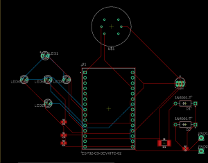
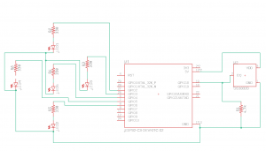
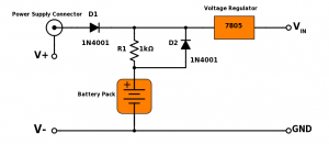
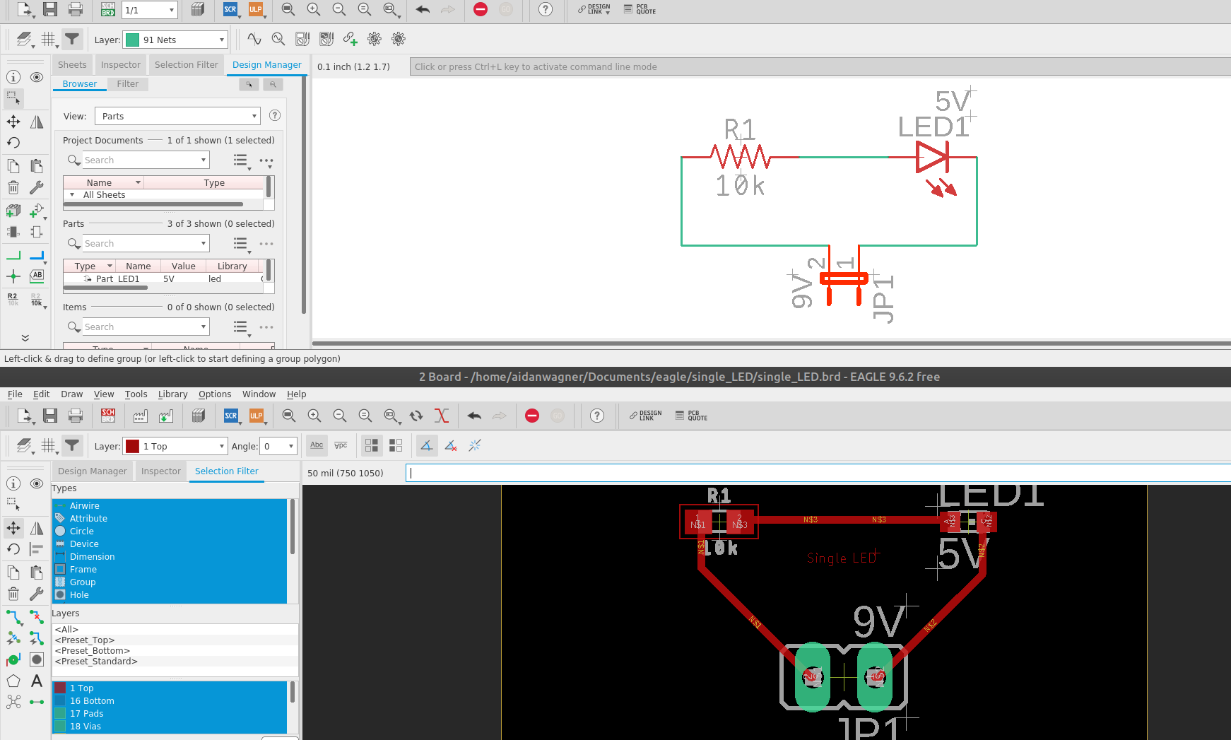
While we were putting these slides together, I noticed an issue with our PCB design. We had our ESP32 being powered directly through the power supply instead of through the battery charging circuit. We knew that this would cause problems, so Neha and I began figuring out a solution for this problem. On monday, I reworked our PCB design to fix this issue, as well as standardize all traces to be .3mm in width. After some final touches, we uploaded the design to JLCPCB and Quinn was able to place the order for us on Tuesday morning. This order was originally supposed to arrive on May 4th, which was a slight issue because the Techspark expo is on May 4th. This would mean that we would not be able to demonstrate our fully assembled node in the way we had hoped. To fix this, Neha and I went back to the PCB room in techspark to make another attempt at doing our own fabrication with our new design. While the fabrication seemed to go well, Neha did run into an issue when soldering our components onto the board: the PCB seemed to melt. I would guess that there must be some way around this issue, but the delivery date on the new PCBs was moved up to May 2nd, so we may be able to use these for the expo instead.

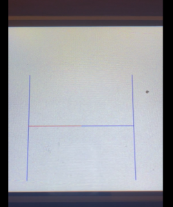
Another aspect of our project that I worked on this week was developing some code that would allow us to sleep our ESP32 to conserve battery power. After a little research, I was able to find that there was a fairly simple way to do this and it seemed to work. However, because our LCD display is powered by the same rails that the ESP32 is powered on, sleeping the ESP32 will not turn off the display. To remedy this, I did some research into the Nextion commands and found that I could send a command to the Nextion display to sleep the screen. After this, I wrote a couple of wrapper functions for this so that they could be called in our main function and this worked successfully. To test this, I set up a circuit that ran our display and an LED from the ESP32. I then attached a multimeter to the circuit to measure the power draw. When the display turned off, the current decreased from ~150mA to ~40mA and then when the ESP went into sleep mode, the current decreased even further to ~10mA. This test is shown in the video below:

https://youtube.com/shorts/vVrOd6ty3pc?feature=share

Currently, the PCBs are a little behind schedule. This is because we needed to reorder the PCBs. However, if they do come by the date that they say they will, we will be able to solder them and have them working by the techspark demo. If this is not the case, then we will plan on soldering our components into protoboards so that we still can still have compact, finished looking nodes. In terms of software, Jason and I split up the power sleeping and distributed pathfinding. I was able to get the power saving software to work so this fits well into our schedule. We also still need to complete our video and poster, but this will happen once we have our system finished. 

In the upcoming week, one very vital thing for us to get done is the PCB assembly. As soon as the PCBs arrive, assembling one of these complete nodes will be Neha’s and my priority. Another thing that I am hoping to achieve is to integrate the power saving code with our current display/pathfinding integration. I don’t think this will be too much work, but it will be important to ensure that the delays caused by sleeping do not mess with our pathfinding algorithm and that we can turn off the power saving once a fire is detected.

Aidan’s Status Report for Apr. 22, 2023

This week I spent the majority of my time getting the PCB design ready for shipping. In order to do this, we first had to make some fixes to the battery circuit and power supply. Last week Neha and I realized that we would not be able to charge the batteries up to 5V with a 5V power supply because it passed through a diode and a resistor which caused a voltage drop. After some testing, we found that we were able to increase the input voltage to at least 7V without damaging the ESP32. From this, we can see that we will be able to use a high enough voltage so that we can still charge our batteries. 

After this, we had to find out how to power our board, and after some research, I decided on a barrel jack that we could solder into our pcb. We are still determining what the output of this power supply will be, so to accommodate for this, I added in two resistors to our PCB design that can act as a voltage divider to ensure that the voltage that we are getting into our main circuit is the right level. After this, there were some other issues that had to be fixed on the PCB. One of these is that we were having trouble with our eagle library file for the temperature sensor. The metal pads were overlapping, so I had to place three holes instead. I also had to reroute all of the traces that were under the ESP32, because the machine we were using was not precise enough to lay traces between the pin holes of the ESP. 

Once the PCB design was finalized, our hope was to create a version ourselves so that we could test it before ordering more online. However, after Neha spent Friday making a PCB with Quinn, we felt that we would not have time to clean up the board to test it, while still ordering the PCBs on time. One remedy that we tried was to use the Bantam machine to see if we could mill a PCB design that we could use for testing, but we had trouble getting the settings right, and we thought that this would also take too long for us to do testing before ordering the PCBs. Finally, Neha and I decided that we would spend time verifying the PCBs and then we would order them. To do this, we wrote out the entire design on a white board system by system and went through each system to make sure that it was wired correctly. In doing this, we were able to find a couple mistakes that we fixed. After this we sent in our order to Quinn to be placed.

Final Design:

Currently the PCB progress is on schedule. We were hoping to have the PCB design sent out for fabrication by now, and we have finished that up. Ideally, this means that we will get the PCBs back this week and we can start assembling them soon. One thing that we are a little behind on is the distributed pathfinding. We have not been focusing on this too much, because we had to get the PCB design finalized, but now that this is done, we will be able to spend more time on the pathfinding and finish this up. We are also a little behind on some of the aspects such as making a video demo and a poster, but I feel that we will be able to finish these tasks once we have our system up and running.

Next week, the first thing that I want to do is to work with Jason and Neha to do our final presentation slides. After this, I want to work with Jason to get the distributed pathfinding completed. Additionally, the PCBs should arrive before the week is over, so I am hoping to start assembling those and placing our components onto the boards. The one other thing that I will do this week is select a power supply and have it ordered so that we can show that our circuit works with wall power and that it charges the batteries. Once we do this, we can also determine the resistors to use in our voltage divider.

Aidan’s Status Report for Apr. 8, 2023

I spent the first half of this week working on getting our interim demo ready for wednesday. The first thing that Neha and I focused on was integrating the LED and LCD displays with the output of the pathfinding code. Originally, we were able to display directions, but after reformatting our code to import the functions that we used, we were able to create a file to run our loop function that could utilize these functions. After integrating, we could specify a path, and the node would show the direction to go (Left, right, up, down) on the LEDs, as well as the path to follow on the LCD display.

The other main thing that I worked on this week was the pcb design. A big part of this was adding the backup battery circuit to our schematic, which is something that Neha and I worked on. After this, I also cleaned up the LED circuitry because I found that I could reduce the number of resistors needed by running the LEDs through one resistor to ground instead of each LED having its own resistor. However, Neha and I did find out that we would not be able to do this for the red and green LEDs together. We attempted to do this on our breadboard and got errors when uploading to our ESP32. I am assuming this is because of the different forward voltages of the LEDs. After making these changes I created a board layout by moving all of the components onto a board in Eagle and using the autorouter. The autorouter returned a board layout that used two layers. I was initially hoping that we would be able to do it on one layer, so I spent some time looking into this and seeing if there are any changes I can make to only use 1 layer.

One of the tests that I am planning on running is testing how long our system can run on the battery supply. For this I want to create a circuit so that I can test all of the components at the same time. Once I can do this, I will see if our system can run for 24 hours straight. 24 hours was our design requirement. To begin this task I will collect all of the software that I need to run the individual pieces. I am hoping to accomplish this this coming week. Another test that I want to conduct is the testing of the system as a whole. Once Neha, Jason, and I’s code is integrated, I think we should begin testing by holding a flame to the nodes and looking for the correct output on our LED and LCD displays. Also, as I mentioned previously, I feel that we need to test our system by wiring it up the same way that our PCB design specifies. After this we will test to make sure that all of the components are working correctly to ensure that our PCB design is valid on wall power and battery power.

This week, one of the tasks that I want to complete is verifying our PCB layout. With the exception of the battery charging circuit, we have tested the individual components separately, but together. This is something that I for sure want to accomplish before we begin manufacturing the final PCBs. This way we can also fine tune resistance values and hole sizes to prevent issues we may have further down the road with our design. Another thing that I wish to accomplish is to integrate the display code with Jasons pathfinding code. Currently we are able to take a path, so I do not think that there will be too much work to integrate these systems. One other taks I want to finish this week is to find a floor plan on campus that we will use to create our video demo. As some of our code will be hardcoded to match the building specifically, having the building in mind may save us some time.

Currently I believe that I am on schedule. There were some changes that we made to our schedule this week, but I believe we covered these changes in our interim demo. Some of these included changes for the PCB because we were thinking that we may make them ourselves. However, I am still on track to finish my tasks on time, according to our new schedule.

Aidan’s Status Report for Apr. 1, 2023

This week, I was a little busy because of two midterms that I had, so I was not able to get as much done as I had hoped, but I was able to make some good progress. First, during class, Neha and I were able to get the smoke sensors working. However, one issue with the setup that we had is that the output was unusable. We tried adjusting this by putting a resistor on the output pin, but this did not seem to help too much. After doing some research on this part, we found that they are often shipped already attached to a PCB. When looking at this PCB, we could see that the sensitivity of the device was set through a potentiometer. I think that using a potentiometer to fine tune our resistance would be a good idea for us as well. Once we have this dialed in, we can decide on a resistor to use for our final PCBs.

For the PCB design, I was still unable to find a library for the MQ2 sensors that we are using. Because of this, I decided that I would have to create my own part. This consisted of 3 stages. First, I had to create a footprint for the device that specified the location of the pads. For this I had to do some mild trigonometry based on the specifications in the datasheet, as these were given in polar coordinates, but Eagle takes rectangular coordinates. Then, I had to create the symbol which just consisted of me creating the shape that would appear on the schematic. Lastly, I had to make the device, connecting the pins of the symbol to the pads of the footprint. After all of this, I was able to add my part to the schematic that I have been working on. I learned a lot about Eagle from this, and I think that this is going to help us as we finish up our PCB design. I was going to add a picture, but I couldn’t get WordPress to accept it, even when I reduced the size.

Lastly, I also met with Jason this week to begin integrating our pathfinding and LCD display code. However, not too long after we started, we realized that we would need to make some changes to the code before they could be integrated. The LCD code was fairly easy to modify, but the pathfinding code will need a few changes before it can be integrated. 

Currently, I am a little behind schedule on the PCB design. Creating the custom smoke detector was one of my goals for this week, and I did complete that, but we had hoped to have this finalized by last week. However, this week, we spent some time looking into alternative fabrication methods, and I believe that by making the PCBs ourselves, we will be able to save some time and money. This is how I think that we can make up the time in our schedule, as we leave a couple weeks in our schedule for manufacturing and delivery. We are also behind in our pathfinding integration and testing, but my schedule this next week is not very busy, so I believe that Jason and I will be able to spend a good amount of time and hopefully finish some of this before the interim demo.

Next week, I am hoping to create a final PCB design that includes all of our components. Including the batteries. I am also hoping to get the display integrated with the pathfinding code. Currently, I have put a pause on the distributed pathfinding, as Jason and I would like to get a version working before we start on the other version. I would also like to look into integrating communication with pathfinding. The one other thing that I need to do is look at battery holders for our AA batteries and pick some to order or 3D print.

Aidan’s Status Report for Mar. 25, 2023

This week, one of the main things I focused on was controlling the display through our microcontroller, rather than just hard coding in images through the microSD card. To start, Neha and I figured out how to send commands through the TX pin on the ESP32 to the Nextion display. We found that we could do this with the Serial.write() function. Initially, we were ableto get two images to switch back and forth after a specified delay with these commands.  After this,  I began by reading up on the instruction set for Nextion commands. From here I learned how to draw lines on the Nextion display. For this, I wrote a C++ program that represents the nodes as x,y locations, and the edges as a list of edges between two nodes. The program initially sends messages to the display to draw the entire maps, and then it has the ability to highlight specific routes by changing their color. For demonstration purposes I made the edges cycle between being red and blue on a delay. I made sure that the interface would be able to easily interface with our pathfinding software so that we will be able to integrate the two together smoothly. It fits in well with the edge list and vertex list representation of a graph.

Another thing that I focused on was finding the libraries for the PCBs that we are making. These library files were surprisingly difficult to find, but I was able to find libraries for our microcontroller and temperature sensors. I spent some time looking for a library for our smoke sensor, but this ended up being very difficult to find. For this, I am looking into making my own library as it is a relatively simple pinout. I also added in 5 LEDs to our diagram, as this is how many we will need for our LED nodes. Each is wired to its own 4.7kOHM resistor and to its own GPIO pin. One thing that I will need to look into is that Eagle is telling me that I need something attached to the reset pin of the ESP32, but I am not sure what we would wire this too at the moment.

Being able to display paths on the Nextion display was one of my main goals for this week, so I am on schedule for that. One thing that I am slightly behind on is the PCB design. We only recently received the smoke sensors because we decided to change the smoke sensors that we are using. Also not being able to find a readily available library for these sensors has pushed my schedule back for this task. Even if I have to make my own library for this part, I think this is something that I can definitely catch up on next week. Also now that we have all of our sensors, I will be able to convert our breadboard circuit to a PCB design. Jason has made a lot of progress with the communication, so I think we will be able to press forward with the tasks that were blocked by this and make up the tasks that we have fallen behind on.

One thing that I am hoping to get done next week is the PCB design. Along with this, I will be doing some research into creating our own PCBs. I want to look into the machines available on campus and how we can get in to use them. Another thing that I am hoping to get done this week is some integration between the communication and path finding. Now that Jason has managed to get communication set up between the nodes, we will be able to use this communication in our pathfinding algorithms. Another important thing that I will do next week is look into AA battery holders that we will use to hold and charge our AA batteries on the nodes.

Aidan’s Status Report for Mar. 18, 2023

One of the first things I did this week was my ethics assignment. I felt that this assignment was helpful because it focused on some of the less obvious impacts that engineering projects can have. For example, at first glance I would not assume that a highway infrastructure could have political implications. This assignment helped me to see that ethics goes beyond power consumption, pollution, etc., and can be less obvious but still very impactful. I also had the opportunity to look into some statistics for generative artificial intelligence that I found very interesting.

There were some parts that we had to order this week, so I ordered the batteries that we needed. We decided to scale down the amount of nodes that we are planning on using, so this also helped us save on the number of batteries that we had to order.

After this, Neha and I spent time working to get our display working. When we first received this display, we were all at a loss for how we were supposed to program it. Initially, we thought that, because there was an application that we had to install on our laptop, we would just plug the board into our laptops and program it through this application. However, then we realized that the adapter for our laptop only supported the board with power, so we knew there had to be a different way. After researching some tutorials, we found that we would create the display code on our laptops, and then upload it to a micro SD card that we could then put into the display. After this, we were able to get a picture of a floor plan showing on our display, which was one of the main things that I wanted to get accomplished this week. After this, Neha and I researched how we would interact with the display through our ESP32, and we found that we would be able to set state variables through the TX pin on our ESP32. We worked at this for some time, but were unable to get it working. We’re planning on working more on this next week.

Another thing that I spent some time working on this week was the communication between ESP32s. I found a tutorial online for connecting two ESP32s through an Ethernet connection. After spending some time working on this, I feel that I will need to do some more research for it in order to get it working. I was able to get the code compiled and uploaded, but for some reason the microcontrollers were unable to begin the TCP connection.

This is the tutorial I was using:

https://esp32io.com/tutorials/communication-between-two-esp32

Getting something to be uploaded to our display was one of my main goals for this week, so finishing that was on schedule for me. One aspect that I have fallen behind in is the network communication. However, I know that Jason has been working on this as well and has made some progress. I feel that this week we will be able to make up for this work. I do not have many tasks in the PCB area right now so this should give me more time to work on the network tasks.

This coming week I would like to get the communication working and have messages sent between the nodes. I would also like to get to the point where we can change what is shown on the display based on our sensor readings. One other thing that I would like to complete next week is to write the message code for my distributed path planning software. This will rely on us having a good understanding of the wifi communication, but I feel that this is something we will be able to do this week.

Aidan’s Status Report for Mar. 4, 2023

This week, I spent the majority of the time working with Jason and Neha on our design report. One of the contributions that I made to this report was the implementation details. Here I provided more specific details that added onto our system architecture section. Additionally, there were sections that we all worked on together. Also, putting this design report together forced us to make some decisions that we were wavering on, such as the batteries. I feel that, now that we have finished this report, we have a much better sense of a concrete direction that we will be proceeding in. Now that our design is complete, we will be able to focus on creating the systems involved in our project.


One decision that I made while we were writing our report was to switch out our batteries. Originally, we were using LiPO batteries with a capacity of 1000mAh and a voltage of 3.6V. However, after more research into the power consumption of our displays, we found that this voltage would not be high enough. We had previously assumed that this capacity would not be enough, based on our calculations, but now that we also found the voltage would not be high enough, we felt that we needed to pivot our choice to a different battery. I found that we could use NiMH with a voltage of 1.2V. After spending a decent amount of time researching the possibility of continuously charging LIPO batteries, I could not find any documentation about a safe way to do this. For  NiMH, I was able to find this information very easily, which made me much more confident about the ability to continuously charge these batteries. We found these for a cheap enough price to stay in our budget, and by using 3 of these batteries for our LED nodes and 6 for our LCD nodes, we would be able to successfully power our nodes. Additionally, the capacity of these batteries is 2000mAh, which satisfies our battery capacity requirement.


Lastly, I also spent some time getting started with our displays. First I downloaded the software required to use these displays. Then I began doing some research on how these boards are programmed. These are the sites that I found and am planning on using when I begin to use these boards:

https://www.instructables.com/Nextion-Display-Interface-With-ESP-32-Four-Relay-B/

https://anywarellc.com/2020/12/29/nextion-touchscreen-with-esp32/#:~:text=Nextion%20has%20a%20nice%20series,to%20support%20HMI%20GUI%20development.

https://www.nutsvolts.com/magazine/article/building-a-programmable-thermostat-with-a-nextion-lcd-display


My schedule was pushed back slightly because of the design report. This took more time than I had previosly thought it would, so I was unable to get to programming the displays. However, there are no current tasks that are blocked by this. I am planning on finishing this task this week, and this will not cause any further delays to our schedule. We also do not have the boards communicating yet, which is behind schedule. However I also believe that we can accomplish this task during this coming week as well. Last week, I had multiple midterms, and this along with the design report occupied much of my time, but now that these are over, I am confident that I will be able to use the extra time to catch up on this work. Next week, I am also planning on working with Jason to get the Zigbee network setup, assuming that the zigbee cards have arrived. Lastly, I also plan on getting a couple of our ESP32s running on wifi, so that I can test out the distributed pathfiniding code that I have written for them. This week, I am also hoping to get some testing done with real fire from a candle to further test our sensors.

Aidan’s Status Report for Feb. 25, 2023

At the beginning of the week, most of my time was spent putting together our design review presentation with Neha and Jason. As we were putting our slides together, we were forced to make finalizing decisions for our project. This process was very helpful in determining exactly what our final product was going to look like. After we had finished our presentation, our group decided that I would present it, so I spent some time rehearsing it, ensuring that I would be able to give the presentation without relying on the information on our slides. We also were not able to use our class time the same way that we were able to in weeks that don’t have presentations, but we met outside of class when we had topics that we needed to discuss.


After this, I began writing up some sections of our design report. I began by writing a rough draft of the abstract and the introduction. For the introduction, I outlined the problem that we are hoping to solve and then proposed our solution to the reader. I focused on excluding technical details, as these seem better suited for further on in the paper. Additionally, I spent some time figuring out how we want to format our use-case requirements. My initial thought was to include the table from our proposal, however after much trial and error, I believe that attempting to create a readable table that is located in the correct spot in Latex may not be the best solution. Unless we can find a way to make this more reader-friendly, I think I may revert to writing our requirements in paragraph form.


Additionally, I spent some time converting my distributed pathfinding software to a version that would be compatible with our ESP32 microcontrollers. Initially, I was using python to quickly develop a prototype, however after some research, we could not find if micropython was supported on ESP32 C-3. Therefore, I decided to use C++ as we know that our microcontrollers are compatible with the Arduino IDE. Before beginning the conversion, I had to do some research on the aspects of C++ that I was hoping to use, however after some refreshing, I was able to begin coding. I was able to complete the code for the structure of our pathfinding software that will run on each node. In essence, each node will check and see if its neighbor is an exit, and if it is, then it will plan its path to the exit. After this initial check, each node will constantly be checking for other paths sent by other nodes. From these sent paths, each node is able to determine the shortest safe path to the exit. Currently, I have placeholder functions for the functions requiring communication(send() and read()), as I will need to look into the protocols and libraries used for Wifi and Zigbee communication. Additionally, the code only supports one exit node at the moment and I am hoping to test this before incorporating multiple exit functionality. Even with these placeholders, the code does compile and can be found here:

https://github.com/jtledon/18-500_Capstone_FireEscape/blob/path_finding/Pathfinding/singleNode.cpp

At the moment, I am on schedule for my tasks. The main technical task that I was hoping to accomplish for this week was to write a C++ version of my pathfinding code. While I did complete this on time, it has made me realize an additional step that I will need to add to my schedule: integrating the pathfinding code with the communication code. One of our tasks for next week is getting our nodes communicating with each other, so after this, I will be able to start writing our necessary write() and read() functions. It does not make sense to run this pathfinding algorithm on just one node because the computation is distributed across all nodes. This means that we will not be testing the functionality  and accuracy of our C++ implementation until we have our communication working. Next week, my top priority is finishing our design report. Additionally, I will be focusing on getting our communication to work, as this is a blocking point to some of our further development. Additionally, I am hoping to get something to display on our sensors next week and figure out how to output to these displays, however, this is only if the displays arrive during this coming week. Lastly, we will have to push back our testing of the smoke sensors as we are still waiting on these to arrive.

Aidan’s Status Report for Feb. 18, 2023

At the beginning of this week, I conducted research on batteries that we can use as backups for our nodes. This involved researching how much power an ESP32 consumes (~40mA on idle, ~120 on active mode) and performing calculations to ensure that our nodes can run on idle mode for 24 hours and 5 minutes on active mode. Through this math, I determined that we would need at least 500mA, but we also decided that depending on the peripherals we are planning to use (Zigbee card and display), we may need more and we were able to find a pack of 10 1000mAh batteries that was within our budget, so we decided to purchase these. Additionally, I researched the circuit that I am planning on using as a backup circuit and this is what I came across:

This is from: https://www.allaboutcircuits.com/projects/battery-backup-power-supplies/

The circuit allows the battery to be charged while it is not being used, but once the power goes out, the battery will be able to power our microprocessor.

This week I also spent a lot of time with my group deciding which items we were going to order for creating our nodes. We were able to find displays that were within our budget and had the functionality and size that we wanted. We also were looking into ESP32 boards that had built in Zigbee functionality that Jason was able to find, but these recently sold out, so we are planning to buy 2 Zigbee boards that we will use to demonstrate our backup network. We our Zigbee network. will plan on setting up our system using Wifi or Bluetooth and then in the case that this system goes out in a fire, we will show that our system can successfully switch to 

Additionally, this week we received our temperature sensors. Neha, Jason and I worked to set up a circuit on our breadboard. After downloading the Arduino packages, we were able to measure the temperature and light up an LED once a threshold was reached. We used a lighter to test the increase in our temperature sensor. 

On my own, I have spent a lot of time getting our distributed path finding algorithm working. This algorithm is described in: https://www.cs.utexas.edu/users/misra/scannedPdf.dir/DistrShortestPath.pdf

, but it essentially involves a bottom up algorithm that builds paths from the nodes closest to the exit, propagating these paths up through the graph. Using the framework that I was able to get working on this week, I have created a simulation that will take in a number of nodes, a list of edges, and a goal node. Then, a separate thread is created for each node and they begin running the pathfinding algorithm. The nodes that are neighbors to the goal node define that they have an edge to the goal and they send this information to their neighbors. The neighbors receive this message, and if it contains a shorter path than their current solution, it is updated to have this shorter path as its solution and it sends this solution to its neighbors. Currently, this code assumes edge lengths of 1, but by adding an extra field to the sent messages, I will be able to specify different lengths for each edge. This code can be found here:

https://github.com/jtledon/18-500_Capstone_FireEscape/blob/path_finding/Pathfinding/functions.py

https://github.com/jtledon/18-500_Capstone_FireEscape/blob/path_finding/Pathfinding/distPathfinding.py


One of the courses that I have used a lot this week is 15-440. In order to make sure our distributed simulation would work correctly when transferred to our physical nodes, I had to take into account the time it can take for messages to be sent, as well as how to receive and handle incoming messages without blocking and freezing the operation of the pathfinding algorithm. I also used what I learned about threads from 15-213 to better understand the simulation that we are using and the simulated nodes running on different threads. Additionally, My time spent in 15-281 and 15-210 helped prepare me to write the pathfinding algorithm as this is covered in both of these classes. For the breadboarding that we were doing, I used what I learned in 18-100 and 18-220. To program our arduino and select valid resistors and circuit elements I had to use information from designing circuits in 18-220. Additionally, when I was performing calculations to determine what battery we needed to power our boards, I had to rely on the knowledge I have about current, voltage, and resistance that I learned in 18-100.

Currently I believe my tasks are on schedule. One of the tasks I was planning to have done this week is breadboarding. We have completed breadboarding for the sensors we have available. The one change to this schedule that we will have to make is that we will add to our breadboarding as our sensors and microprocessors arrive. We will continue to add to our circuit and once the boards come, we will switch from breadboarding with an arduino to breadboarding with our new microprocessors. My distributed path finding algorithm is now running on a laptop on my distributed simulation which was my goal for this week, and I am planning on converting it to code that can run on a microprocessor next week. I am also planning on running further tests on my current code to iron out any bugs that may be present. However, one setback is that we will need to wait until we have our microprocessors and communication setup to test the distributed pathfinding. This coming week, in addition to converting my distributed pathfinding code, I plan on working with Jason to get the LED’s to light up on our Arduino (or other microprocessor if they arrive by then) based on the solution of our pathfinding algorithms. In addition, I plan on working to add our smoke sensors to our breadboard if they come early, although they estimated arrival is March 1st.

Aidan’s Status Report for Feb. 11, 2023

At the beginning of this week, I worked with Neha and Jason to complete our proposal. The two most time consuming parts of this were creating our schedule and finalizing our requirements. To finish our requirements, we had to do a lot of research on fire codes and industry standards for fire alarm systems. However, now that we have completed these, I feel that the schedule and requirements will really help us to structure our project. Unfortunately, I tested positive for COVID this week and was unable to attend class, but Neha and Jason were able to Facetime me into class so that I could still watch the presentations.

Later this week, I began by researching PCB design software, and I decided that Eagle would be the best option for us, as Neha and I have both used it before in 18-349 and it is available to us through CMU. Additionally, I found an Eagle tutorial that I could follow to learn how to design PCBs from scratch. This involved creating a PCB with an LED, a jumper, and a resistor. Through, this I learned how to lay out the boards, download components online, and go see the process from start to finish. This was the completed schematic and board:

Additionally, I set out to create a platform where we can test our pathfinding algorithm. I wanted this platform to be able to simulate our distributed nodes, but in a simple way so that we can focus on the algorithm and not get hung up on implementation details. After some research, I found a github repository, Distributed_System_Simulator-DSS_py, that provides a framework to allow multiple python processes to talk with one another. To begin, I wrote an introductory program that involved 10 different processes that talked with one another. This will serve as a basis for once we want to have our nodes communicate with each other for our pathfinding algorithm.

After this, I began to set up a test suite for our pathfinding. I know that testing will be incredibly important as we begin to develop our software. I decided to use pytest for this and currently have created a test file containing some basic tests. As we continue to work on our algorithm, we can easily define more tests and run them by running “pytest”. This will provide an easy to read output for us as we progress. This code has been pushed to our github:

https://github.com/jtledon/18-500_Capstone_FireEscape/blob/path_finding/Pathfinding/distPathfinding.py

https://github.com/jtledon/18-500_Capstone_FireEscape/blob/path_finding/Pathfinding/functions.py

https://github.com/jtledon/18-500_Capstone_FireEscape/blob/path_finding/Pathfinding/test_pathfinding.py

Currently, my Eagle research is on target, as the hope was to have it up and running and used by now. Our Eagle research will be put on hold for now, as we will want to figure out our design through breadboarding. We will have a better idea of our schedule for breadboarding once we order our parts and see when they will arrive. Jason has path finding running on a laptop, which was our goal for this week, and I feel that the work that I have put toward testing this in a distributed simulation, will allow us to reach next week’s goal of having the path-finding running on  Arduinos on time. This will require Jason and me to combine the work that we have been doing and ensure test that the algorithm we choose is running correctly on a laptop. Then we will transfer this code to the Arduino’s.