Team Status Report 3/25

Currently the largest risk is still the wireless charging not working correctly. We received the wireless charging kit this week, but since everyone was busy with their own weekly tasks, the wireless charging was not tested beyond basic verification that it worked.  Additionally, we are worried about the functionality of the wireless charging through the 3D printed housing. We can mitigate the risk of the wireless charging not delivering enough power somewhat by lowering the idle power consumption of the key device, thus allowing the battery to trickle charge with an extremely low current input. As for the housing, it would be possible to make the bottom wall of the housing extra thin to allow for minimal interference with the wireless charging coils. Another risk is that the configurator software may not be able to precisely identify which of the keys is being programmed at any given time. We plan to mitigate this using numbered keycaps on top of each key, such that it would be possible to select a key to be programmed. Alternatively, we could have a system where the user needs to press a key, which would highlight it on the interface and allow the user to set a command.

The spec has not changed in the last week, and no additional costs have been incurred.

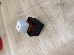
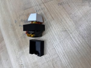
Attached below are photos of the key programming interface prototype and the key housing prototype.

Ben’s Status Report 3/25

This week I soldered another 2 BLE boards together and worked more on the software side of things. First, I added debouncing to the peripheral code to ensure that the interrupt would no longer cause a race condition when it was called multiple times in rapid succession due to switch bounce. This caused issues with key reading so I switched the key reading system such that it would toggle the value upon detecting a state change instead, which would save power from reading the keypin all the time. I also played around with the delay in the main loop such that it would connect to the central device quickly without using up too much power. Next, I set up event handlers for the BLE events of connection and disconnection, having them stop and restart the advertising respectively. This would further save on power as the device would no longer need to advertise constantly even though it was already connected to a central. On the central side of things, I fixed up the reconnection such that instead of taking upwards of 30 seconds to reconnect, reconnection could happen within a second or so. Additionally, other keys can still be used while a key or multiple keys are reconnecting since the reconnection does not spin anymore while waiting for a connection like before. However, to facilitate this, I had to also add BLE event handlers for connection and disconnection that would start and stop the scan for the particular device UUID so as to reduce function call overhead for the reconnection of a device. I also helped fit the key stack onto the first prototype of the 3D printed housing. It ended up being too large and without a cutout for the USB, so adjustments will be made in the future.

I believe my progress is on schedule this week.

Next week I plan on working on the central code such that it will be capable of connecting to new key devices beyond just the scan phase. This will mean that if a user brings in new keys, they can be connected right away without a reset of the central receiver. Additionally, this means that if a key was not detected immediately, it can be connected later still.

Zhejia’s Status Report 3/18

This week I worked on creating a prototype for the keyboard firmware that acts as an interface between the key receiver and the computer. I prototyped this on the Arduino Nano 33 IoT, since the Arduino Keyboard library was not compatible with the Seeed Xiao boards. However, this caused a few issues since to get the keyboard working, a new driver was needed for the Nano 33 IoT. Additionally, I had to make sure the right version of the Keyboard and USB libraries were installed, as there were some issues posted online with the keyboard device not being recognized in certain versions. Finally, I modified the KeyReceiver code to be able to distinguish between the individual key presses and send a different character as a keyboard depending on which key was pressed.

I am on schedule this week since I was scheduled to work on the keyboard programming software, and having the Arduino being able to act as a keyboard was an important first step to this.

Next week, I hope to finish the code template that the keyboard customization software will edit and flash to the main board.

Ben’s Status Report 3/18

This week I worked on implementing multiple connections with the central receiver. I managed to get 4 keys working since we only had 4 batteries in total. I also figured out the layout of the battery, switch, and board. Originally, we planned to have the battery sandwiched between the two boards (the Seeed and the single switch PCB). However, after some consideration, I determined it would be too difficult to solder consistently while keeping everything in place. Thus, I modified the design to have the Seeed flipped with the single switch PCB stacked on the back of the board and the battery on the front. This allowed easier access to the reset switch and protected the battery connection. Using this design, I soldered together 2 boards. I also soldered the Mill Max sockets onto the PCBs, which allowed hot-swapping of the switches. On the software side, I managed to get interrupt based signaling working. This means that the peripherals will only attempt to send data over if a key is pressed, and sleep otherwise, thus saving power. Additionally, I set the rest of the pins on the board to be input pullup to reduce power draw further. Finally, on the receiver side, I managed to get reconnection working. However, this reconnection is very slow, taking up to 30 seconds in some cases. To test sizing and consistency. Overall, this design ended up with a thickness of 15mm, which gives us 7mm of space for the wireless charging module.

I believe my progress is on schedule, since this week I was slated to work on the connection of multiple switches and the housing. I have the rough dimensions of the housing finalized thanks to finally having the height of entire assembly set, and I have also managed to connect 4 separate boards to the central receiver. Next week I hope to assemble more boards and reduce the latency of reconnection and optimize the interrupts more. Currently the interrupts occasionally lock up the board, requiring a reset. I hope to figure out how to resolve this issue next week as well.

Team Status Report 3/11

Currently, we believe the most significant risks are that the wireless charging may not be able to deliver enough current to charge the battery sufficiently quickly and that the timeline may not allow for sufficient time to iterate both the programming software and the design of the 3D printed housing by the time the project is due. In terms of wireless charging, we are managing the risk by focusing development on getting a single switch to wireless charge correctly as a proof of concept, and having the remaining switches charge from USB as a backup. In terms of the software, we plan to focus on functionality first and then add any aesthetic improvements only if we have time. The same goes for the 3D printed housing. We may have to end up sacrificing some of the dimension design requirements to get the housing working at first, but then we plan to see what we can shave down after the fact.

We added a single switch PCB as an interface between the Cherry MX switch and the Seeed board. This was necessary as we found that our original plan of soldering wires between the switches and Seeed board would not meet the requirement of having hotswap capabilities. Additionally, it would make assembly nearly impossible as the switch would have to somehow be soldered inside the housing. This incurs an additional $1.50 cost per switch, but since the PCBs are so simple, it would cost a lot less if we ordered custom PCBs (~$5 on JLPCB). However, since we want to begin putting everything together more quickly, Amazon seemed to be the better choice. With this change, we may need to increase the dimensions of the housing to occupy a footprint of 25mmx22mm as current measurements of the battery + seeed setup already are pushing 22mm in the length dimension. We believe that this will not present that large of a usability issue however, since that is about the difference in spacing between a laptop keyboard and a Cherry MX style keyboard, and thus we do not expect users to be able to notice a difference.

There are no updates to the schedule currently. We have attached images of our charging testing and a video of the two switch connection working.

New tools:

To design the software, we would need to learn some sort of GUI creation library like PyGUI or GTK. To design the 3D printed housing, we plan on learning how to design using Autodesk, since it allows us to import Eagle footprints in order to give us an idea of the dimensions of the Seeed board and other components.

Video link: https://youtu.be/-SggOrEHb1I

Ben’s Status Report 3/11

This week I worked on implementing the connection between multiple Seeed BLE boards and a central controller. To facilitate this, I modified the peripheral code, having each Seeed board’s characteristic utilize the notify function to allow the central board to subscribe to multiple peripherals at once. Unfortunately, because I only brought 2 Seeed boards home, I had to buy a Arduino Nano 33 IoT to test the multi board connection. Luckily, the BLE library worked fine with the board and I was able to test the central connecting with two peripherals simultaneously. The code has been updated on the github to reflect these changes. I also wrote the Introduction, Use-Case requirements, Architecture, and Design Requirements sections of the design report and helped with the Design studies, Summary, and Glossary of Terms.

This work puts me a bit ahead of schedule since I believe this will allow me to scale up to multiple switch devices without much hassle.

Next week I plan to get multiple keys working and, when the single switch PCBs get here, solder together the switch breakout board with the Seeed boards and test their stability.

Here is a video of the two key receiver working: https://youtu.be/-SggOrEHb1I

Ben’s Status Report 2/25

This week I rewrote the entirety of the BLE code such that each key peripheral device “daisy chains” off the previous one, forwarding the values of each key to the central controller. However, I was unable to get this fully working as I had to solve a few issues with getting ArduinoBLE to make a device act both as a central and a peripheral. The current code can be found here: bojuns/FP-Key-A_BLE (github.com)

Still, however, I believe my progress is on track since after some more debugging, I believe I should be able to get multiple connections working before the end of next week.

Next week I hope to finish the daisy chaining protocol and test it for latency measurements.

Weekly Status Report 2/18

We believe the most significant risks currently involve getting the custom PCBs in on time and getting the wireless charging current high enough. We would like to have a 50mA charging current minimum, which would hopefully reach our target of under 8 hours charging time with buffer to spare. However, our current charging capabilities of < 1mA would mean that charging the battery to full would take astronomically long. Like last week, our backup plan if the PCBs do not get here on time, is to use one of the SEEEDs as a central receiver. For the charger, our backup plan is to use the USB port attached to a wireless charging pad.

There were some changes to the wireless charging setup, which are documented in Zhejia’s individual status report. This change was necessary to reach the minimum charging voltage on the SEEED. This does not incur many additional costs, as we still need to design the custom PCBs.

Our schedule remains unchanged.

Wireless working:

https://youtube.com/shorts/qfVXAoujZhY?feature=share

Ben’s Status Report 2/18

https://youtube.com/shorts/qfVXAoujZhY?feature=share

This week, I got a single key to communicate via BLE to a controller. When the key was pressed, an LED on the switch and receiver will light up. I first started by finding an appropriate BLE library for arduino, which ended up being ArduinoBLE. From here, I defined a ledService for turning on and off the LED with a ByteCharacteristic to send the key press state. Debugging and troubleshooting took a lot of time because sometimes the device would fail to connect, but after a reset or a reflash, would work all of a sudden. This was solved after removing the serial initialization, when I realized that the device would lose power after being unplugged and before switching over to LIPO power, which caused the code to run again, which led it to continuously wait for a serial connection to the computer.

I believe my progress is on schedule, as I am scheduled to have a single key working this week. From what I gathered, I believe implementing multiple keys will not be too difficult.

Next week, I will try to implement multiple keys communicating with the central microcontroller, where each key module will be able to wireless transmit the pressed or unpressed state to the key.

18-220 was a great help to the progress this week, as it introduced me to the Arduino IDE and how to install various packages and program the correct board. Additionally, I applied my 18-349 experience of reading datasheets to determine pinouts and functionality (which is how I determined which pins to hook up the switch and the battery to). Additionally, Embedded taught me how to use minicom, which helped with debugging (since the Arduino IDE only lets you open a single serial terminal at once). Finally, the programming knowledge was learned during the last 2 weeks when I was researching the BLE protocol and how to implement it through arduino.

Zhejia’s Status Report 2/11

I worked on the inductive charger, first making my own coil, then trying on some coils I acquired for more testing. I first calculated that the resonant frequency would be around 24 kHz, with the inductance of 43 microhenries in series with a capacitor of 1 microfarads. However, experimentally, I found that the real resonant frequency was very difficult to measure accurately as simply switching the direction of the probes would change the frequency at which I measured the highest output voltage for a given 5v input. Eventually, I settled on a ~41kHz resonant frequency for the inductor, which gave me an output voltage of ~3.4v (with a 5v input), which is close to the charging voltage for our planned small LIPO batteries, but I believe more investigation is required for the strange resonant measurement behavior.

We are mostly on schedule, having ordered/acquired the experimental parts needed, but the strange resonant behavior did put us a little behind schedule for proof of concept, which I will work on more with Korene next week to resolve. Asking staff may be an option as well.

In the next week, we will finish the proof of concept and create the circuit that integrates and stabilizes the magnetic charging for integration with the boards *when* they get here. (To be clear, the boards will likely not get here next week).